
Homework Answers


Add Answer to:
2. (25 points) For the given ideal transformer in Fig. (a), where /10 Ω, and ZL...
Problem E1.2.6 (20 points) Consider the magntically coupled circuit that involves an ideal transformer as depicted...
 Problem E1.2.6 (20 points) Consider the magntically coupled circuit that involves an ideal transformer as depicted in Figure E1.2.6. The sinusoidal voltage source frequency is 20 x 103 (rad/sec). The load connected to the secondary winding (RHS of the ideal transformer) consists of a variable resistor R in series with a variable capacitor C. (a) Find the values of R and C for maximum power transfer from the voltage source in the primary winding. (b) What is the maximum average...
Palred Quiz) 3 For ideal transformer as shown in figure P.3, determine: a. The currents I1,...
 Palred Quiz) 3 For ideal transformer as shown in figure P.3, determine: a. The currents I1, I2 and I3! b. The primary and secondary voltage Vu V, Vg and Va C. The complex power supplied by the source! d. The effective power dissipated by the load impedance, Zioad 812-20 Ω 1:3 18 Ω Zload 40200 v ( 45 Figure P.3 Ideal Transformer Circuit
In the circuit shown in Fig. I, T is an ideal transformer whose turns ratio n/n...
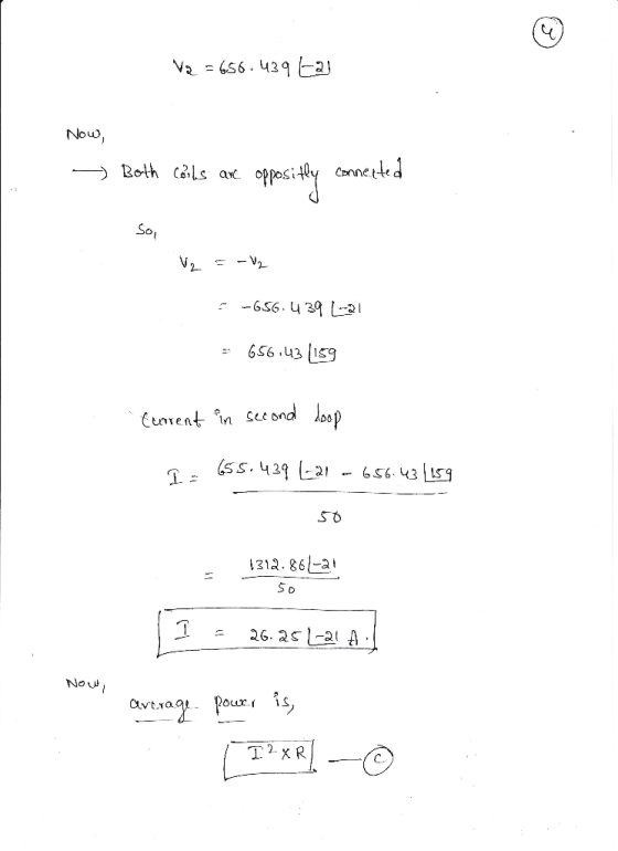
 In the circuit shown in Fig. I, T is an ideal transformer whose turns ratio n/n is 2, where ni and n are the number of turns of the primary winding and the number of turns of the secondary winding, respectively; V is a sinusoidal voltage source whose phasor voltage is 240v2 L45 V; ZI and Z2 are two loads and their impedances are Z1-8Q, Z2-2p. Find phasor current i1, i2 and phasor voltage V1 and V2 Z1 V1 Fig.
4.41 Consider ạ 25 kVA, 240°/240 V, 60 Hz transformer with Z,-2.533 +J2.995 Ω and Z, = (2.5333 + ...
 4.41 Consider ạ 25 kVA, 240°/240 V, 60 Hz transformer with Z,-2.533 +J2.995 Ω and Z, = (2.5333 + )2.995) 10-2 S2, referred to the primary and secondary sides, respectively. b) The transformer is connected at the receiving end of a feeder that has an impedance of 0.3 +j 1.8 Ω. Let the sending end-voltage magnitude of the feeder be 2400 V. Also there is a load connected to the secondary side of the transformer that draws rated current from...
9.6 Consider the ideal dc-to-ac inverter shown in Fig. P9.6. Assume Si/S4 and S2/S3 are switched...
 9.6 Consider the ideal dc-to-ac inverter shown in Fig. P9.6. Assume Si/S4 and S2/S3 are switched alternatively at a 50% duty cycle with a switch period of T. Let the output current be given by , (t) , sin at, where ω 2π/T. (a) Derive the expression for the instantaneous power delivered to the load. (b) Determine the average power delivered to the load. (c) Discuss the requirement for a practical switch implementation for si- (d) Repeat part (c) for...
Q6. A 50 Hz, 25 kVA 7200/240 V transformer has the following equivalent circuit parameters: Prima...
 Please show full working
Q6. A 50 Hz, 25 kVA 7200/240 V transformer has the following equivalent circuit parameters: Primary resistance-1562, secondary resistance-0.02 Ω Primary leakage reactance-140Q, Secondary leakage reactance-0.15Q, Magnetising reactance 30 k2, Core loss resistance 200 k2 (a) The transformer is connected to two loads in parallel. The first load is 10 kW at 0.866 power factor lagging and the second load is 15kVA with a power factor of 0.8 lagging. Find the percentage regulation and power efficiency...
Please show full working
Q6. A 50 Hz, 25 kVA 7200/240 V transformer has the following equivalent circuit parameters: Primary resistance-1562, secondary resistance-0.02 Ω Primary leakage reactance-140Q, Secondary leakage reactance-0.15Q, Magnetising reactance 30 k2, Core loss resistance 200 k2 (a) The transformer is connected to two loads in parallel. The first load is 10 kW at 0.866 power factor lagging and the second load is 15kVA with a power factor of 0.8 lagging. Find the percentage regulation and power efficiency...
Q6. A 50 Hz, 25 kVA 7200/240 V transformer has the following equivalent circuit parameters: Prima...
 Help me answer c and d
Q6. A 50 Hz, 25 kVA 7200/240 V transformer has the following equivalent circuit parameters: Primary resistance-1562, secondary resistance-0.02 Ω Primary leakage reactance-140Q, Secondary leakage reactance-0.15Q, Magnetising reactance 30 k2, Core loss resistance 200 k2 (a) The transformer is connected to two loads in parallel. The first load is 10 kW at 0.866 power factor lagging and the second load is 15kVA with a power factor of 0.8 lagging. Find the percentage regulation and...
Help me answer c and d
Q6. A 50 Hz, 25 kVA 7200/240 V transformer has the following equivalent circuit parameters: Primary resistance-1562, secondary resistance-0.02 Ω Primary leakage reactance-140Q, Secondary leakage reactance-0.15Q, Magnetising reactance 30 k2, Core loss resistance 200 k2 (a) The transformer is connected to two loads in parallel. The first load is 10 kW at 0.866 power factor lagging and the second load is 15kVA with a power factor of 0.8 lagging. Find the percentage regulation and...
Please show all your work clearly and write out explanations. I know the solution involves a cotangent equation but...
 Please show all your work clearly and write out
explanations. I know the solution involves a cotangent equation but
I don't know where it comes from. Can you please show a derivation
for that equation? thanks
Problem 2.29 A 50-MHz generator with Z, 50 2 is connected to a load 2L = (50_/25) Ω The time-average power transferred from the generator into the load is maximum when Zg = , where ZL is the complex this condition without changing Zg,...
Please show all your work clearly and write out
explanations. I know the solution involves a cotangent equation but
I don't know where it comes from. Can you please show a derivation
for that equation? thanks
Problem 2.29 A 50-MHz generator with Z, 50 2 is connected to a load 2L = (50_/25) Ω The time-average power transferred from the generator into the load is maximum when Zg = , where ZL is the complex this condition without changing Zg,...
Problem 3 a- List five different transformer types used in the electric power system. [5 points]...
 Problem 3 a- List five different transformer types used in the electric power system. [5 points] Consider a three-winding transformer, as shown in Figure 1, with the following particulars Ze 0.01+j 0.08 V2-440 z,= 0.01 tj 0.08 2-100/-25 Z- 0.01 +j 0.08 s-80/-35° Assume that V2 is the reference phasor, calculate: (a) The intermediate voltage Vo (3 points) (b) The primary current l and the primary voltage V. (3 points) (c) The tertiary voltage Vs referred to the primary side....
Consider the circuit shown in the figure where R1 = R2 = 225 Ω , L1...
 Consider the circuit shown in the figure where
R1 = R2 = 225 Ω ,
L1 = 25 mH , L2
= 50 mH , C = 1.25
μF ,V0 = 85 V ,
and ω = 60 s−1 . (Figure 1)
1. Find the power dissipated by R1.
2. Find the power dissipated by R2.
3. At what frequency or frequencies will both resistors
dissipate the same power?
If you need to enter more than one answer, enter them in
ascending order, separated by commas....
Consider the circuit shown in the figure where
R1 = R2 = 225 Ω ,
L1 = 25 mH , L2
= 50 mH , C = 1.25
μF ,V0 = 85 V ,
and ω = 60 s−1 . (Figure 1)
1. Find the power dissipated by R1.
2. Find the power dissipated by R2.
3. At what frequency or frequencies will both resistors
dissipate the same power?
If you need to enter more than one answer, enter them in
ascending order, separated by commas....
 Problem E1.2.6 (20 points) Consider the magntically coupled circuit that involves an ideal transformer as depicted in Figure E1.2.6. The sinusoidal voltage source frequency is 20 x 103 (rad/sec). The load connected to the secondary winding (RHS of the ideal transformer) consists of a variable resistor R in series with a variable capacitor C. (a) Find the values of R and C for maximum power transfer from the voltage source in the primary winding. (b) What is the maximum average...
 Palred Quiz) 3 For ideal transformer as shown in figure P.3, determine: a. The currents I1, I2 and I3! b. The primary and secondary voltage Vu V, Vg and Va C. The complex power supplied by the source! d. The effective power dissipated by the load impedance, Zioad 812-20 Ω 1:3 18 Ω Zload 40200 v ( 45 Figure P.3 Ideal Transformer Circuit
 In the circuit shown in Fig. I, T is an ideal transformer whose turns ratio n/n is 2, where ni and n are the number of turns of the primary winding and the number of turns of the secondary winding, respectively; V is a sinusoidal voltage source whose phasor voltage is 240v2 L45 V; ZI and Z2 are two loads and their impedances are Z1-8Q, Z2-2p. Find phasor current i1, i2 and phasor voltage V1 and V2 Z1 V1 Fig.
 4.41 Consider ạ 25 kVA, 240°/240 V, 60 Hz transformer with Z,-2.533 +J2.995 Ω and Z, = (2.5333 + )2.995) 10-2 S2, referred to the primary and secondary sides, respectively. b) The transformer is connected at the receiving end of a feeder that has an impedance of 0.3 +j 1.8 Ω. Let the sending end-voltage magnitude of the feeder be 2400 V. Also there is a load connected to the secondary side of the transformer that draws rated current from...
 9.6 Consider the ideal dc-to-ac inverter shown in Fig. P9.6. Assume Si/S4 and S2/S3 are switched alternatively at a 50% duty cycle with a switch period of T. Let the output current be given by , (t) , sin at, where ω 2π/T. (a) Derive the expression for the instantaneous power delivered to the load. (b) Determine the average power delivered to the load. (c) Discuss the requirement for a practical switch implementation for si- (d) Repeat part (c) for...
 Please show full working
Q6. A 50 Hz, 25 kVA 7200/240 V transformer has the following equivalent circuit parameters: Primary resistance-1562, secondary resistance-0.02 Ω Primary leakage reactance-140Q, Secondary leakage reactance-0.15Q, Magnetising reactance 30 k2, Core loss resistance 200 k2 (a) The transformer is connected to two loads in parallel. The first load is 10 kW at 0.866 power factor lagging and the second load is 15kVA with a power factor of 0.8 lagging. Find the percentage regulation and power efficiency...
Please show full working
Q6. A 50 Hz, 25 kVA 7200/240 V transformer has the following equivalent circuit parameters: Primary resistance-1562, secondary resistance-0.02 Ω Primary leakage reactance-140Q, Secondary leakage reactance-0.15Q, Magnetising reactance 30 k2, Core loss resistance 200 k2 (a) The transformer is connected to two loads in parallel. The first load is 10 kW at 0.866 power factor lagging and the second load is 15kVA with a power factor of 0.8 lagging. Find the percentage regulation and power efficiency...
 Help me answer c and d
Q6. A 50 Hz, 25 kVA 7200/240 V transformer has the following equivalent circuit parameters: Primary resistance-1562, secondary resistance-0.02 Ω Primary leakage reactance-140Q, Secondary leakage reactance-0.15Q, Magnetising reactance 30 k2, Core loss resistance 200 k2 (a) The transformer is connected to two loads in parallel. The first load is 10 kW at 0.866 power factor lagging and the second load is 15kVA with a power factor of 0.8 lagging. Find the percentage regulation and...
Help me answer c and d
Q6. A 50 Hz, 25 kVA 7200/240 V transformer has the following equivalent circuit parameters: Primary resistance-1562, secondary resistance-0.02 Ω Primary leakage reactance-140Q, Secondary leakage reactance-0.15Q, Magnetising reactance 30 k2, Core loss resistance 200 k2 (a) The transformer is connected to two loads in parallel. The first load is 10 kW at 0.866 power factor lagging and the second load is 15kVA with a power factor of 0.8 lagging. Find the percentage regulation and...
 Please show all your work clearly and write out
explanations. I know the solution involves a cotangent equation but
I don't know where it comes from. Can you please show a derivation
for that equation? thanks
Problem 2.29 A 50-MHz generator with Z, 50 2 is connected to a load 2L = (50_/25) Ω The time-average power transferred from the generator into the load is maximum when Zg = , where ZL is the complex this condition without changing Zg,...
Please show all your work clearly and write out
explanations. I know the solution involves a cotangent equation but
I don't know where it comes from. Can you please show a derivation
for that equation? thanks
Problem 2.29 A 50-MHz generator with Z, 50 2 is connected to a load 2L = (50_/25) Ω The time-average power transferred from the generator into the load is maximum when Zg = , where ZL is the complex this condition without changing Zg,...
 Problem 3 a- List five different transformer types used in the electric power system. [5 points] Consider a three-winding transformer, as shown in Figure 1, with the following particulars Ze 0.01+j 0.08 V2-440 z,= 0.01 tj 0.08 2-100/-25 Z- 0.01 +j 0.08 s-80/-35° Assume that V2 is the reference phasor, calculate: (a) The intermediate voltage Vo (3 points) (b) The primary current l and the primary voltage V. (3 points) (c) The tertiary voltage Vs referred to the primary side....
 Consider the circuit shown in the figure where
R1 = R2 = 225 Ω ,
L1 = 25 mH , L2
= 50 mH , C = 1.25
μF ,V0 = 85 V ,
and ω = 60 s−1 . (Figure 1)
1. Find the power dissipated by R1.
2. Find the power dissipated by R2.
3. At what frequency or frequencies will both resistors
dissipate the same power?
If you need to enter more than one answer, enter them in
ascending order, separated by commas....
Consider the circuit shown in the figure where
R1 = R2 = 225 Ω ,
L1 = 25 mH , L2
= 50 mH , C = 1.25
μF ,V0 = 85 V ,
and ω = 60 s−1 . (Figure 1)
1. Find the power dissipated by R1.
2. Find the power dissipated by R2.
3. At what frequency or frequencies will both resistors
dissipate the same power?
If you need to enter more than one answer, enter them in
ascending order, separated by commas....
Most questions answered within 3 hours.
-
Where is the error in this code sequence?
String s1 = "Hello";
String s2 = "ello";...
asked 10 months ago -
Financial data for Joel de Paris, Inc., for last year
follow:
Joel de Paris, Inc.
Balance...
asked 10 months ago -
Consider this reaction:
Al2(SO4)3 (aq)+ BaCl3
(aq) Al2Cl6 (aq)- +
3BaSO4(s) . What is the...
asked 10 months ago -
Suppose that Savneet is considering increasing her
recent random sample from 20 car rentals to 40...
asked 10 months ago -
Trucks arrive at an unloading terminal at an average rate of 120
per hour.
Trucks arrive...
asked 10 months ago -
Why are methanol and ethanol completely soluble in water while
octanol is not very little soluble....
asked 10 months ago -
A facilities manager at a university reads in a research report
that the mean amount of...
asked 10 months ago -
When the CuSO4 is rehydrated by adding water to the anhydrous
compound, is this an endothermic...
asked 10 months ago -
A ray of sunlight is passing from diamond into crown glass; the
angle of incidence is...
asked 10 months ago -
A block of mass 0.249 kg is placed on top of a light, vertical
spring of...
asked 10 months ago -
how do the kidneys compensate in the presences of acidosis
a) trigger hyperventilate
b) reserve acid...
asked 10 months ago -
Question 501 pts
The rental rate of capital to the firm increases. Which of the
following...
asked 10 months ago