![QUESTION 5 [15 marks] In the circuit shown in Figure 9, find 1(1). 19 OF 24V 2H 10 sin(t – 30°) v € 222} 2 cos 3t 3422](http://img.homeworklib.com/questions/e88bee10-8abd-11eb-9867-0162308cf08d.png?x-oss-process=image/resize,w_560)
Homework Answers


Add Answer to:
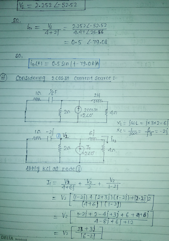
QUESTION 5 [15 marks] In the circuit shown in Figure 9, find 1(1). 19 OF 24V...
Question 1 An electronic circuit is shown in Figure 1. In order to simulate the circuit,...
 Question 1 An electronic circuit is shown in Figure 1. In order to simulate the circuit, a transfer function is needed. a) Is this an open loop or closed loop process? Justify your answer. (3 marks) b) Find the transfer function V.(s) for the electrical network shown in Figure 1. V:(s) (10 marks) c) What is the order of the process? (2 marks) d) Determine the roots of the transfer function and comment on the stability of the process. (5...
Please solve it in the simplest possible way 1. In the circuit shown in Figure 1,...
 Please solve it in the simplest possible way
1. In the circuit shown in Figure 1, v.(t) = 10 cos(2t-30) V. Find (t). 22 1H vs 1F +v(1) Fig. 1 2. In the circuit shown in Figure 2, determine i(t). i(t) 20 2mH MM 100 5 cos 2000 V ) +50 uF 3200 Fig. 2 3. Find v (t) in the circuit of Figure 3 if the current i, = 2sin (100) A. 22 i 1.22 v S1222 + -j...
Please solve it in the simplest possible way
1. In the circuit shown in Figure 1, v.(t) = 10 cos(2t-30) V. Find (t). 22 1H vs 1F +v(1) Fig. 1 2. In the circuit shown in Figure 2, determine i(t). i(t) 20 2mH MM 100 5 cos 2000 V ) +50 uF 3200 Fig. 2 3. Find v (t) in the circuit of Figure 3 if the current i, = 2sin (100) A. 22 i 1.22 v S1222 + -j...
Question 1 (5 marks): For the circuit shown in Figure 1 below, find the number of...
 Question 1 (5 marks): For the circuit shown in Figure 1 below, find the number of nodes, branches and loops, then use mesh analysis to find the currents and the power on dissipated in the 100, 10 and 120 resistors 1003 3120 ww 9A 412 Fig. 1
Question 1 For the circuit shown in figure 1; i. Find the transfer impedance function, H(s)...
 Question 1 For the circuit shown in figure 1; i. Find the transfer impedance function, H(s) = Vds(s) Find the poles and zeros for this transfer function and plot them on the s - Find the magnitude of the transfer function in decibels. [10] s-plane [8] ii [3] 2H 20 20 2 H Figure Question 2 The hybrid parameters (h-parameters) for the two -port network circuit in figure 2 are; 5 h=2 0.05 Find the equivalent impedance parameters (z-parameters) Find...
.) An unbalanced Y-Y circuit is shown in Figure 2. Find the average power delivered to...
 .) An unbalanced Y-Y circuit is shown in Figure 2. Find the average power delivered to the load. 21H 10 cos (4t - 90°) 20 2H 10 cos 4150°) 4Ω 2H 10 cos (4t + 30°) Source Line Load Figure 2
b) A periodic voltage vs(t) is applied to a RLC circuit shown in Figure 1 (b)...
 b) A periodic voltage vs(t) is applied to a RLC circuit shown in Figure 1 (b) with R=10012, L=100mH and C=1pF. The first four nonzero terms in the Fourier series is given by the following: v:(t) = 10 +2 sin(10’t)-1sin(2x10't)+sin(3x10°r) v Find the first four nonzero terms in the Fourier series of the steady-state current iſt). (20 marks) R M v.(t) Tv.(t) Figure 2(b): Circuit for Question 2
19, 20 2020 Question 2 (Marks: 15) You are performing a practical experiment with the circuit...
 19, 20 2020 Question 2 (Marks: 15) You are performing a practical experiment with the circuit in figure 2a. You have performed all your calculations but at the end you notice that the voltage source does not give you 115cos(t) Volts but 121.cos(t + 8) Volts. You do not want to redo all your calculations so instead you decide to insert an impedance Zx into the circuit as in figure2b to balance out the voltage. 1Ω 1Ω 1Ω ZX 1Ω...
QUESTION 2 [10 MARKS Assuming the op-amp circuit shown in Figure 2 to be ideal. Find...
 QUESTION 2 [10 MARKS Assuming the op-amp circuit shown in Figure 2 to be ideal. Find the transfer function of the circuit. E,(s) [10 marks] G(s) R3 R1 A B R2 eo(t) e(t) C2 Figure 2 +
1) The source vokage of the circuit shown in Figure 4 is v. = 20 cos(39)...
 1) The source vokage of the circuit shown in Figure 4 is v. = 20 cos(39) V. Determine ico) an 1.) z2(t). The source voltage of the circuit shown in Figure 4 is vs = 20 cos(3t) V. Determine i(t) and ། { [t AA ཆ ༽ ཐ 3༽ ། 1 ད་ ༢༥༣ 'A 3རིན་
5. [20 marks Consider the RC series circuit shown in Fig. 3. Determine the overall output...
 5. [20 marks Consider the RC series circuit shown in Fig. 3. Determine the overall output y(t). Determine the steady state output, yss(t), of the circuit if the input signal is given by r(t) = sin (3t) u(t) x(t) = sin(31) C = 0.5 μF Figure 3: RC series circuit for Q5
 Question 1 An electronic circuit is shown in Figure 1. In order to simulate the circuit, a transfer function is needed. a) Is this an open loop or closed loop process? Justify your answer. (3 marks) b) Find the transfer function V.(s) for the electrical network shown in Figure 1. V:(s) (10 marks) c) What is the order of the process? (2 marks) d) Determine the roots of the transfer function and comment on the stability of the process. (5...
 Please solve it in the simplest possible way
1. In the circuit shown in Figure 1, v.(t) = 10 cos(2t-30) V. Find (t). 22 1H vs 1F +v(1) Fig. 1 2. In the circuit shown in Figure 2, determine i(t). i(t) 20 2mH MM 100 5 cos 2000 V ) +50 uF 3200 Fig. 2 3. Find v (t) in the circuit of Figure 3 if the current i, = 2sin (100) A. 22 i 1.22 v S1222 + -j...
Please solve it in the simplest possible way
1. In the circuit shown in Figure 1, v.(t) = 10 cos(2t-30) V. Find (t). 22 1H vs 1F +v(1) Fig. 1 2. In the circuit shown in Figure 2, determine i(t). i(t) 20 2mH MM 100 5 cos 2000 V ) +50 uF 3200 Fig. 2 3. Find v (t) in the circuit of Figure 3 if the current i, = 2sin (100) A. 22 i 1.22 v S1222 + -j...
 Question 1 (5 marks): For the circuit shown in Figure 1 below, find the number of nodes, branches and loops, then use mesh analysis to find the currents and the power on dissipated in the 100, 10 and 120 resistors 1003 3120 ww 9A 412 Fig. 1
 Question 1 For the circuit shown in figure 1; i. Find the transfer impedance function, H(s) = Vds(s) Find the poles and zeros for this transfer function and plot them on the s - Find the magnitude of the transfer function in decibels. [10] s-plane [8] ii [3] 2H 20 20 2 H Figure Question 2 The hybrid parameters (h-parameters) for the two -port network circuit in figure 2 are; 5 h=2 0.05 Find the equivalent impedance parameters (z-parameters) Find...
 .) An unbalanced Y-Y circuit is shown in Figure 2. Find the average power delivered to the load. 21H 10 cos (4t - 90°) 20 2H 10 cos 4150°) 4Ω 2H 10 cos (4t + 30°) Source Line Load Figure 2
 b) A periodic voltage vs(t) is applied to a RLC circuit shown in Figure 1 (b) with R=10012, L=100mH and C=1pF. The first four nonzero terms in the Fourier series is given by the following: v:(t) = 10 +2 sin(10’t)-1sin(2x10't)+sin(3x10°r) v Find the first four nonzero terms in the Fourier series of the steady-state current iſt). (20 marks) R M v.(t) Tv.(t) Figure 2(b): Circuit for Question 2
 19, 20 2020 Question 2 (Marks: 15) You are performing a practical experiment with the circuit in figure 2a. You have performed all your calculations but at the end you notice that the voltage source does not give you 115cos(t) Volts but 121.cos(t + 8) Volts. You do not want to redo all your calculations so instead you decide to insert an impedance Zx into the circuit as in figure2b to balance out the voltage. 1Ω 1Ω 1Ω ZX 1Ω...
 QUESTION 2 [10 MARKS Assuming the op-amp circuit shown in Figure 2 to be ideal. Find the transfer function of the circuit. E,(s) [10 marks] G(s) R3 R1 A B R2 eo(t) e(t) C2 Figure 2 +
 1) The source vokage of the circuit shown in Figure 4 is v. = 20 cos(39) V. Determine ico) an 1.) z2(t). The source voltage of the circuit shown in Figure 4 is vs = 20 cos(3t) V. Determine i(t) and ། { [t AA ཆ ༽ ཐ 3༽ ། 1 ད་ ༢༥༣ 'A 3རིན་
 5. [20 marks Consider the RC series circuit shown in Fig. 3. Determine the overall output y(t). Determine the steady state output, yss(t), of the circuit if the input signal is given by r(t) = sin (3t) u(t) x(t) = sin(31) C = 0.5 μF Figure 3: RC series circuit for Q5
Most questions answered within 3 hours.
-
Where is the error in this code sequence?
String s1 = "Hello";
String s2 = "ello";...
asked 10 months ago -
Financial data for Joel de Paris, Inc., for last year
follow:
Joel de Paris, Inc.
Balance...
asked 10 months ago -
Consider this reaction:
Al2(SO4)3 (aq)+ BaCl3
(aq) Al2Cl6 (aq)- +
3BaSO4(s) . What is the...
asked 10 months ago -
Suppose that Savneet is considering increasing her
recent random sample from 20 car rentals to 40...
asked 10 months ago -
Trucks arrive at an unloading terminal at an average rate of 120
per hour.
Trucks arrive...
asked 10 months ago -
Why are methanol and ethanol completely soluble in water while
octanol is not very little soluble....
asked 10 months ago -
A facilities manager at a university reads in a research report
that the mean amount of...
asked 10 months ago -
When the CuSO4 is rehydrated by adding water to the anhydrous
compound, is this an endothermic...
asked 10 months ago -
A ray of sunlight is passing from diamond into crown glass; the
angle of incidence is...
asked 10 months ago -
A block of mass 0.249 kg is placed on top of a light, vertical
spring of...
asked 10 months ago -
how do the kidneys compensate in the presences of acidosis
a) trigger hyperventilate
b) reserve acid...
asked 10 months ago -
Question 501 pts
The rental rate of capital to the firm increases. Which of the
following...
asked 10 months ago