

Homework Answers
Add Answer to:
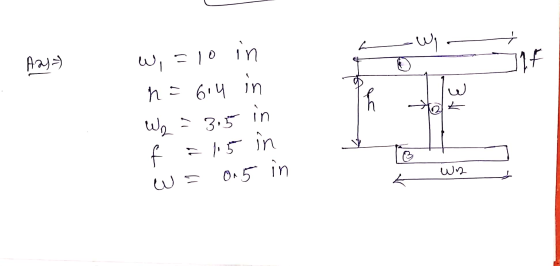
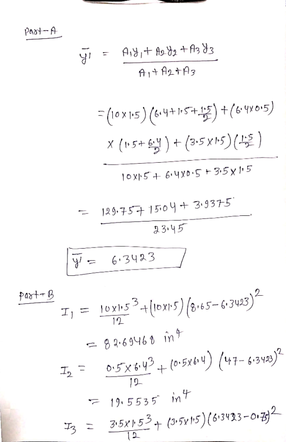
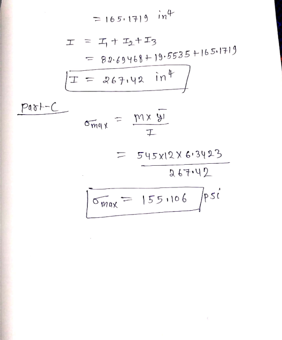
u Review Part B - Calculate the moment of inertia Learning Goal: To find the centroid...
Learning Goal: To calculate the shear stress at the web/flange joint in a beam and use...
 Learning Goal: To calculate the shear stress at the web/flange joint in a beam and use that stress to calculate the required nail spacing to make a built- up beam. A built up beam can be constructed by fastening flat plates together. When an l-beam is subjected to a shear load, internal shear stress is developed at every cross section, with longitudinal shear stress balancing transverse shear stress. If the beam is built up using plates, the fasteners used must...
The Flexure Formula 6 of 6 Learning Goal: To determine an I-beam's maximum bending moment, moment...
 The Flexure Formula 6 of 6 Learning Goal: To determine an I-beam's maximum bending moment, moment of inertia using the parallel-axis theorem, and the maximum stress at a given location using the flexure formula. As shown, I-beam ABC supports a sign that weighs S 27 lb. The I-beam is 24 in. long and is further supported by a rod that is attached 16 in. from the wall. Assume that all forces acting on the I-beam act along its centroid and...
Review Learning Goal: To use the superposition principle to find the state of stress on a...
 Review Learning Goal: To use the superposition principle to find the state of stress on a beam under multiple loadings The beam shown below is subjected to a horizontal force P via the rope wound around the pulley. The state of stress at point A is to be determined. Part A - Support Reactions and Internal Loading Determine the support reactions Cy and Cz and the internal normal force, shear force, and moment on the cross-section containing point A. Express...
Part A - Moment about the x axis at A Learning Goal: To determine the state...
 Part A - Moment about the x axis at A Learning Goal: To determine the state of stress in a solid rod using the principle of superposition. A solid rod has a diameter of e = 60 mm and is subjected to the loading shown. Let a = 200 mm, b = 220 mm c = 340 mm, d = 230 mm, and P = 4.0 kN. Take point A to be at the top of the circular cross-section. (Figure...
b) Calculate moment of inertia of cross section about the z' axis that passes the center...
 b) Calculate moment of inertia of cross section about the z' axis that passes the center of area 0 as shown in the figure. (find center of area y first) YE d-3 in Sin S.S in s in c) ( D ) The max shear stress in a solid round shaft subjected only to torsion occurs: a) on principal planes b) on planes containing the axis of the shaft c) on the surface of the shaft d) only on planes...
Learning Goal: To calculate the normal and shear stresses at a point on the cross section...
 Learning Goal: To calculate the normal and shear stresses at a point on the cross section of a column. The state of stress at a point is a description of the normal and shear stresses at that point. The normal stresses are generally due to both internal normal force and internal bending moment. The net result can be obtained using the principle of superposition as long as the deflections remain small and the response is elastic. Figure < 1 of...
then considered to complete the spec"Katin. Part C Maximum Distributed Load The bending design consideration requires t...
 then considered to complete the spec"Katin. Part C Maximum Distributed Load The bending design consideration requires the calculation of the beam's section modulus. This is a property based solely on the geometry of the beam, specifically the moment of inertia and the centroid Determine the maximum uniform distributed load w that can be applied to the W12 x 14 beam shown below if the maximum allowable bending stress is Ơallow-10 ksi and the maximum allowable shear is Tallow-2.1 ksi. The...
For the beam shown in the given figure:
 For the beam shown in the given figure: (a) Express the internal shear (V) and moment (M) in the beam as a function of x. (b) Draw the shear force diagram (SFD) and bending moment diagram (BMD). (c) If the area moment of inertia (I) of the beam's cross section about the neutral axis is 301.3 (10-6)m4, determine the absolute maximum bending stress (σmax) in the beam.
Learning Goal: To use the superposition principle to find the state of stress on a beam...
 Learning Goal: To use the superposition principle to find the state of stress on a beam under multiple loadings. The beam shown below is subjected to a horizontal force P via the rope wound around the pulley. The state of stress at point A is to be determined. P 1d4 di dz d2 20 mm T 100 mm 200 mm 15 mm 20 mm 150 mm The dimensions are di = 1.85 m, d2 = 0.5 m, dz = 0.9...
Part A - Support Reactions and Internal Loading Learning Goal: To use the superposition principle to...
 Part A - Support Reactions and Internal Loading Learning Goal: To use the superposition principle to find the state of stress on a beam under multiple loadings. The beam shown below is subjected to a horizontal force P via the rope wound around the pulley. The state of stress at point A is to be determined Determine the support reactions Cy and Cand the internal normal force, shear force, and moment on the cross-section containing point A Express your answers,...
 Learning Goal: To calculate the shear stress at the web/flange joint in a beam and use that stress to calculate the required nail spacing to make a built- up beam. A built up beam can be constructed by fastening flat plates together. When an l-beam is subjected to a shear load, internal shear stress is developed at every cross section, with longitudinal shear stress balancing transverse shear stress. If the beam is built up using plates, the fasteners used must...
 The Flexure Formula 6 of 6 Learning Goal: To determine an I-beam's maximum bending moment, moment of inertia using the parallel-axis theorem, and the maximum stress at a given location using the flexure formula. As shown, I-beam ABC supports a sign that weighs S 27 lb. The I-beam is 24 in. long and is further supported by a rod that is attached 16 in. from the wall. Assume that all forces acting on the I-beam act along its centroid and...
 Review Learning Goal: To use the superposition principle to find the state of stress on a beam under multiple loadings The beam shown below is subjected to a horizontal force P via the rope wound around the pulley. The state of stress at point A is to be determined. Part A - Support Reactions and Internal Loading Determine the support reactions Cy and Cz and the internal normal force, shear force, and moment on the cross-section containing point A. Express...
 Part A - Moment about the x axis at A Learning Goal: To determine the state of stress in a solid rod using the principle of superposition. A solid rod has a diameter of e = 60 mm and is subjected to the loading shown. Let a = 200 mm, b = 220 mm c = 340 mm, d = 230 mm, and P = 4.0 kN. Take point A to be at the top of the circular cross-section. (Figure...
 b) Calculate moment of inertia of cross section about the z' axis that passes the center of area 0 as shown in the figure. (find center of area y first) YE d-3 in Sin S.S in s in c) ( D ) The max shear stress in a solid round shaft subjected only to torsion occurs: a) on principal planes b) on planes containing the axis of the shaft c) on the surface of the shaft d) only on planes...
 Learning Goal: To calculate the normal and shear stresses at a point on the cross section of a column. The state of stress at a point is a description of the normal and shear stresses at that point. The normal stresses are generally due to both internal normal force and internal bending moment. The net result can be obtained using the principle of superposition as long as the deflections remain small and the response is elastic. Figure < 1 of...
 then considered to complete the spec"Katin. Part C Maximum Distributed Load The bending design consideration requires the calculation of the beam's section modulus. This is a property based solely on the geometry of the beam, specifically the moment of inertia and the centroid Determine the maximum uniform distributed load w that can be applied to the W12 x 14 beam shown below if the maximum allowable bending stress is Ơallow-10 ksi and the maximum allowable shear is Tallow-2.1 ksi. The...
 Learning Goal: To use the superposition principle to find the state of stress on a beam under multiple loadings. The beam shown below is subjected to a horizontal force P via the rope wound around the pulley. The state of stress at point A is to be determined. P 1d4 di dz d2 20 mm T 100 mm 200 mm 15 mm 20 mm 150 mm The dimensions are di = 1.85 m, d2 = 0.5 m, dz = 0.9...
 Part A - Support Reactions and Internal Loading Learning Goal: To use the superposition principle to find the state of stress on a beam under multiple loadings. The beam shown below is subjected to a horizontal force P via the rope wound around the pulley. The state of stress at point A is to be determined Determine the support reactions Cy and Cand the internal normal force, shear force, and moment on the cross-section containing point A Express your answers,...
Most questions answered within 3 hours.
-
Where is the error in this code sequence?
String s1 = "Hello";
String s2 = "ello";...
asked 11 months ago -
Financial data for Joel de Paris, Inc., for last year
follow:
Joel de Paris, Inc.
Balance...
asked 11 months ago -
Consider this reaction:
Al2(SO4)3 (aq)+ BaCl3
(aq) Al2Cl6 (aq)- +
3BaSO4(s) . What is the...
asked 11 months ago -
Suppose that Savneet is considering increasing her
recent random sample from 20 car rentals to 40...
asked 11 months ago -
Trucks arrive at an unloading terminal at an average rate of 120
per hour.
Trucks arrive...
asked 11 months ago -
Why are methanol and ethanol completely soluble in water while
octanol is not very little soluble....
asked 11 months ago -
A facilities manager at a university reads in a research report
that the mean amount of...
asked 11 months ago -
When the CuSO4 is rehydrated by adding water to the anhydrous
compound, is this an endothermic...
asked 11 months ago -
A ray of sunlight is passing from diamond into crown glass; the
angle of incidence is...
asked 11 months ago -
A block of mass 0.249 kg is placed on top of a light, vertical
spring of...
asked 11 months ago -
how do the kidneys compensate in the presences of acidosis
a) trigger hyperventilate
b) reserve acid...
asked 11 months ago -
Question 501 pts
The rental rate of capital to the firm increases. Which of the
following...
asked 11 months ago