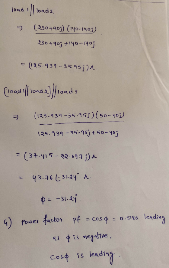
The three loads in the circuit in the figure can be described as follows: Load 1 is a 230 Ω resistor in series with an inductive reactance of 90 Ω ; load 2 is a capacitive reactance of 140 Ω in series with a 140 Ω resistor; and load 3 is a 50 Ω resistor in series with a capacitive reactance of 40 Ω . The frequency of the voltage source is 60 Hz.

Part G: Give the power factor of the composite load seen by the voltage source.
Part H: Give the reactive factor of the composite load seen by the voltage source.
Homework Answers


Add Answer to:
The three loads in the circuit in the figure can be described as
follows: Load 1...
-An electric load consists of a 4Ω resistance, 6Ω inductive reactance and 9Ω capacitive reactance connected...
 -An electric load consists of a 4Ω resistance, 6Ω inductive reactance and 9Ω capacitive reactance connected in series. The total impedance of the load is connected across a voltage source of 120 V: a) Compute the power factor of the load. Pf- b) Compute the source current c) Compute the real power of the circuit. d) Compute the reactive power of the circuit. Isource
1) What is the power outlet for an rms voltage of a standard 220 V? 2)...
1) What is the power outlet for an rms voltage of a standard 220 V? 2) Consider a driven RLC series AC circuit. At frequency f1 the capacitive reactance is twice the inductive reactance. Determine frequency f2 as a function of f1 so that the inductive reactance is twice the capacitive reactance. 3) A standard 120V ac source, connecting wires, and two ideal identical transformers are available. Each transformer has a different number of turns in the two coils. How...
An RLC circuit consists of an alternating voltage source with RMS voltage 90 V and frequency...
An RLC circuit consists of an alternating voltage source with RMS voltage 90 V and frequency 100 Hz, 180 ohm resistor, 200mH inductor, and a 900 micro-F capacitor, all wired in series. A) What is inductive reactance of the circuit? B) What is the capacitive reactance of the circuit?C) What is the impedance of the circuit? D)What is RMS current in the circuit?E) If the frequency is adjustable what frequency should you use to maximize the current in the circuit?
An RLC circuit consists of an alternating voltage source with RMS voltage 90 V and frequency 100 Hz
An RLC circuit consists of an alternating voltage source with RMS voltage 90 V and frequency 100 Hz, a 180 Ohm resistor a 200 ml inductor, and a 900 micro-F capacitor, all wired in series. a) What is the inductive reactance of the circuit? b) What is the capacitive reactance of the circuit? c) What is the Impedance of the circuit? d) What is the RMS current in the circuit? e) of the frequency is adjustable, what frequency should you use to maximize the current...
A series AC circuit contains a resistor, an inductor of 200 mH, a capacitor of 4.30...
A series AC circuit contains a resistor, an inductor of 200 mH, a capacitor of 4.30 µF, and a source with ΔVmax = 240 V operating at 50.0 Hz. The maximum current in the circuit is 180 mA. (a) Calculate the inductive reactance. Ω (b) Calculate the capacitive reactance. Ω (c) Calculate the impedance. kΩ (d) Calculate the resistance in the circuit. kΩ (e) Calculate the phase angle between the current and the source voltage. °
QUESTION 29 An RLC circuit consists of an alternating voltage source with RMS voltage 130 V...
 QUESTION 29 An RLC circuit consists of an alternating voltage source with RMS voltage 130 V and frequency 65 Hz, a 90 Ohm resistor, a 130 mH inductor, and a 200 micro-F capacitor, all wired in series. a) What is the inductive reactance of the circuit? b) What is the capacitive reactance of the circuit? c) What is the impedance of the circuit? d) What is the RMS current in the circuit? e) If the frequency is adjustable, what frequency...
Two electrical loads are connected in parallel to a 380 V, 50 Hz, three phase supply....
Two electrical loads are connected in parallel to a 380 V, 50 Hz, three phase supply. The first load consists of three identical impedance each 7 Ω resistance and 5Ω inductive resistance, connected in star. The second load consists of three identical impedances, each 12 Ω resistance and 8 Ω capacitive reactance connected in delta. Sketch the arrangement described above Calculate Zph1 and Zph2[Zph1= 8.6Ω 35.54°; Zph2= 14.42 Ω -33.69°] Determine Iph1 and Iph2[Iph1= 25.51A -35.54°; Iph2= 26.35A +33.69°] IL1...
A series AC circuit contains a resistor, an inductor of 250 mH, a capacitor of 4.50...
 A series AC circuit contains a resistor, an inductor of 250 mH, a capacitor of 4.50 uF, and a source with AV = 240 V operating at 50.0 Hz. The max maximum current in the circuit is 170 mA. (a) Calculate the inductive reactance. The inductive reactance depends on the value of the inductance and the frequency of the source. Q (b) Calculate the capacitive reactance. (c) Calculate the impedance. kn (d) Calculate the resistance in the circuit. kn. (e)...
Consider an RLC circuit where a resistor (R = 35.0 Ω), capacitor (C = 15.5 μF),...
Consider an RLC circuit where a resistor (R = 35.0 Ω), capacitor (C = 15.5 μF), and inductor (L = 0.0940 H) are connected in series with an AC source that has a frequency of 80.0 Hz. a. Determine the capacitive reactance at this frequency. b. Determine the inductive reactance at this frequency. c. Determine the total impedance. d. Determine the phase angle. e. Determine the circuit’s resonant frequency.
12. A sinusoidal voltage Δv = (75.0 V)sin(120t) is applied to a series RLC circuit with...
12. A sinusoidal voltage Δv = (75.0 V)sin(120t) is applied to a series RLC circuit with L = 20.0 mH, C = 130.0 μF, and R = 32.0 Ω. (a) What is the impedance of the circuit? Ω (b) What is the maximum current in the circuit? A 11.An AC power source has an rms voltage of 120 V and operates at a frequency of 60.0 Hz. If a purely inductive circuit is made from the power source and a...
 -An electric load consists of a 4Ω resistance, 6Ω inductive reactance and 9Ω capacitive reactance connected in series. The total impedance of the load is connected across a voltage source of 120 V: a) Compute the power factor of the load. Pf- b) Compute the source current c) Compute the real power of the circuit. d) Compute the reactive power of the circuit. Isource
 QUESTION 29 An RLC circuit consists of an alternating voltage source with RMS voltage 130 V and frequency 65 Hz, a 90 Ohm resistor, a 130 mH inductor, and a 200 micro-F capacitor, all wired in series. a) What is the inductive reactance of the circuit? b) What is the capacitive reactance of the circuit? c) What is the impedance of the circuit? d) What is the RMS current in the circuit? e) If the frequency is adjustable, what frequency...
 A series AC circuit contains a resistor, an inductor of 250 mH, a capacitor of 4.50 uF, and a source with AV = 240 V operating at 50.0 Hz. The max maximum current in the circuit is 170 mA. (a) Calculate the inductive reactance. The inductive reactance depends on the value of the inductance and the frequency of the source. Q (b) Calculate the capacitive reactance. (c) Calculate the impedance. kn (d) Calculate the resistance in the circuit. kn. (e)...
Most questions answered within 3 hours.
-
Where is the error in this code sequence?
String s1 = "Hello";
String s2 = "ello";...
asked 11 months ago -
Financial data for Joel de Paris, Inc., for last year
follow:
Joel de Paris, Inc.
Balance...
asked 11 months ago -
Consider this reaction:
Al2(SO4)3 (aq)+ BaCl3
(aq) Al2Cl6 (aq)- +
3BaSO4(s) . What is the...
asked 11 months ago -
Suppose that Savneet is considering increasing her
recent random sample from 20 car rentals to 40...
asked 11 months ago -
Trucks arrive at an unloading terminal at an average rate of 120
per hour.
Trucks arrive...
asked 11 months ago -
Why are methanol and ethanol completely soluble in water while
octanol is not very little soluble....
asked 11 months ago -
A facilities manager at a university reads in a research report
that the mean amount of...
asked 11 months ago -
When the CuSO4 is rehydrated by adding water to the anhydrous
compound, is this an endothermic...
asked 11 months ago -
A ray of sunlight is passing from diamond into crown glass; the
angle of incidence is...
asked 11 months ago -
A block of mass 0.249 kg is placed on top of a light, vertical
spring of...
asked 11 months ago -
how do the kidneys compensate in the presences of acidosis
a) trigger hyperventilate
b) reserve acid...
asked 11 months ago -
Question 501 pts
The rental rate of capital to the firm increases. Which of the
following...
asked 11 months ago