
Homework Answers

Add Answer to:
Consider the following circuit with x and z as the input and the output respectively. Determine...
1. Determine for items listed below for this flip-flop circuit. a) Determine for input, output and...
 1. Determine for items listed below for this flip-flop circuit. a) Determine for input, output and state variables b) Determine the excitation and next state equation c) Determine the output equation d) Draw the state table e) Draw the state diagram PR F2 D a CLK Fa 0 CL PR D HD PCLK a FI CLOCK
NAND Problem 3 (30 points) Consider the circuit shown alongside. Notice that there is one A input...
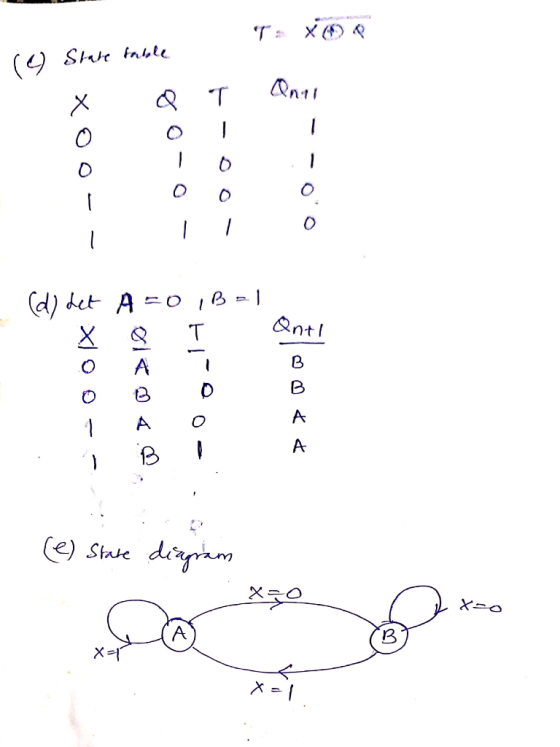
 NAND Problem 3 (30 points) Consider the circuit shown alongside. Notice that there is one A input x and one output. FULL ADDER XOR (a) [5 points] Determine the B Q Cout Clk flip-flop input equations and xin the output z in terms of the present states A, B and input variable x in other words 4-1 compute T, J, K and z. MUX (b) [10 points] Use the above 1 equations to derive the state- 01 table. Assume the...
A SEQUENCE DETECTOR that detects the sequence 00 must be designed whose present output z(k) is set to one when the past input u(k-1) is zero and the present input u(k) is also zero
 Question #2. Design of a Sequential Circuit: A SEQUENCE DETECTOR that detects the sequence 00 must be designed whose present output z(k) is set to one when the past input u(k-1) is zero and the present input u(k) is also zero, where for the other three possible combinations of the input pair u(k-1), u(k) the present output z(k) is set to zero. The state diagram for a sequential circuit that detects the input sequence 00 discussed above is given below:a) Complete...
1. A sequential circuit has one JK flip-flop A, one input x, and one output y....
 1. A sequential circuit has one JK flip-flop A, one input x, and one output y. The flip-flop input equation and circuit output equation are: (a) Draw the logic diagram of the circuit (b) Tabulate the state table of the circuit (P. S., Input, N. S., Output). (c) Draw the state diagram. (d) Derive the state equation A(t+ 1). (e) Starting from state A 0 in the state diagram, determine the state transitions and output sequence that will be generated...
Design a 5-bit binary counter using JK flip flops. Draw the flip-flop circuit diagram, the state...
Design a 5-bit binary counter using JK flip flops. Draw the flip-flop circuit diagram, the state graph, the timing diagram, the truth table (with clk pulse) and the state table (with present and next states).
x is a successive circuit with 1 input and one z output flip flop input and...
x is a successive circuit with 1 input and one z output flip flop input and output equations are as follows. a) Draw the block diagram of the circuit. b) Explain whether the circuit is a Mealy or Moore circuit. c) Analyze the behavior of the circuit A(t+1)=A’B’X B(t+1)= A+C’X’+BCX C(t+1)= AX+CX’+A’B’X’ Y= A’X
The sequential circuit shown below has two flip-flops A and B and one input x. It...
 The sequential circuit shown below has two flip-flops A and B and one input x. It consists of a combinatorial logic connected to the flip-flops, as shown in the Figure 1. Below. Analyze the sequential circuit below: A J A' K Q lo B 2-to-1 MUX Y J Q 11 S B K CLK Figure 1a. Sequential Circuit a) Derive the next state equations for the sequential circuit above: find expressions for JA and KA and Jb and KB as...
21.When a clocked RS flip-flop circuit is in its set state, the output is A. Q...
21.When a clocked RS flip-flop circuit is in its set state, the output is A. Q = 0; Q = 1. B. Q = 0; Q = 0. C. Q = 1; Q = 0. D. Q = 1; Q = 1. 22. An encoding matrix is used to A. convert the comparator outputs of an A/D to a digital word. B. convert digital to analog signals. C. do binary to hexadecimal conversion. D. represent all of the values of...
A Moore sequential circuit Y has two inputs (Xi and X2) and one output (Z). Z begins at 0. It becomes 1 when X1 = 1 and X2 = 1 either concurrently, or one after the other (in either order).
 A Moore sequential circuit Y has two inputs (Xi and X2) and one output (Z). Z begins at 0. It becomes 1 when X1 = 1 and X2 = 1 either concurrently, or one after the other (in either order). Z returns to zero when X1= X2 = 0. The following input and output sequences should help you understand the requirements: X1= 01001000110110 X2 = 00110011000100 Z = (0) 00111000110110 (Hint: Y has 4 states and you may consider defining the 4 states with...
Referring to the circuit in Figure 2 and the corresponding function table in Table 5 on...
 Referring to the circuit in Figure 2 and the corresponding function table in Table 5 on page 5, answer the following questions: a) Draw the state diagram of the circuit (b) (5 Marks) Work out the logic circuit for the Output Block using only NAND gates and inverters. (5 Marks) (c) Give a brief description on the functional characteristics of the circuit in Figure 2 (2 Marks) (d) Redesign the circuit using only one flip-flop and some logic gates. You...
 1. Determine for items listed below for this flip-flop circuit. a) Determine for input, output and state variables b) Determine the excitation and next state equation c) Determine the output equation d) Draw the state table e) Draw the state diagram PR F2 D a CLK Fa 0 CL PR D HD PCLK a FI CLOCK
 NAND Problem 3 (30 points) Consider the circuit shown alongside. Notice that there is one A input x and one output. FULL ADDER XOR (a) [5 points] Determine the B Q Cout Clk flip-flop input equations and xin the output z in terms of the present states A, B and input variable x in other words 4-1 compute T, J, K and z. MUX (b) [10 points] Use the above 1 equations to derive the state- 01 table. Assume the...
 1. A sequential circuit has one JK flip-flop A, one input x, and one output y. The flip-flop input equation and circuit output equation are: (a) Draw the logic diagram of the circuit (b) Tabulate the state table of the circuit (P. S., Input, N. S., Output). (c) Draw the state diagram. (d) Derive the state equation A(t+ 1). (e) Starting from state A 0 in the state diagram, determine the state transitions and output sequence that will be generated...
 The sequential circuit shown below has two flip-flops A and B and one input x. It consists of a combinatorial logic connected to the flip-flops, as shown in the Figure 1. Below. Analyze the sequential circuit below: A J A' K Q lo B 2-to-1 MUX Y J Q 11 S B K CLK Figure 1a. Sequential Circuit a) Derive the next state equations for the sequential circuit above: find expressions for JA and KA and Jb and KB as...
 Referring to the circuit in Figure 2 and the corresponding function table in Table 5 on page 5, answer the following questions: a) Draw the state diagram of the circuit (b) (5 Marks) Work out the logic circuit for the Output Block using only NAND gates and inverters. (5 Marks) (c) Give a brief description on the functional characteristics of the circuit in Figure 2 (2 Marks) (d) Redesign the circuit using only one flip-flop and some logic gates. You...
Most questions answered within 3 hours.
-
Where is the error in this code sequence?
String s1 = "Hello";
String s2 = "ello";...
asked 10 months ago -
Financial data for Joel de Paris, Inc., for last year
follow:
Joel de Paris, Inc.
Balance...
asked 10 months ago -
Consider this reaction:
Al2(SO4)3 (aq)+ BaCl3
(aq) Al2Cl6 (aq)- +
3BaSO4(s) . What is the...
asked 10 months ago -
Suppose that Savneet is considering increasing her
recent random sample from 20 car rentals to 40...
asked 10 months ago -
Trucks arrive at an unloading terminal at an average rate of 120
per hour.
Trucks arrive...
asked 10 months ago -
Why are methanol and ethanol completely soluble in water while
octanol is not very little soluble....
asked 10 months ago -
A facilities manager at a university reads in a research report
that the mean amount of...
asked 10 months ago -
When the CuSO4 is rehydrated by adding water to the anhydrous
compound, is this an endothermic...
asked 10 months ago -
A ray of sunlight is passing from diamond into crown glass; the
angle of incidence is...
asked 10 months ago -
A block of mass 0.249 kg is placed on top of a light, vertical
spring of...
asked 10 months ago -
how do the kidneys compensate in the presences of acidosis
a) trigger hyperventilate
b) reserve acid...
asked 10 months ago -
Question 501 pts
The rental rate of capital to the firm increases. Which of the
following...
asked 10 months ago