. The beam in Figure P5.26 has its central half enlarged so that the moment of...
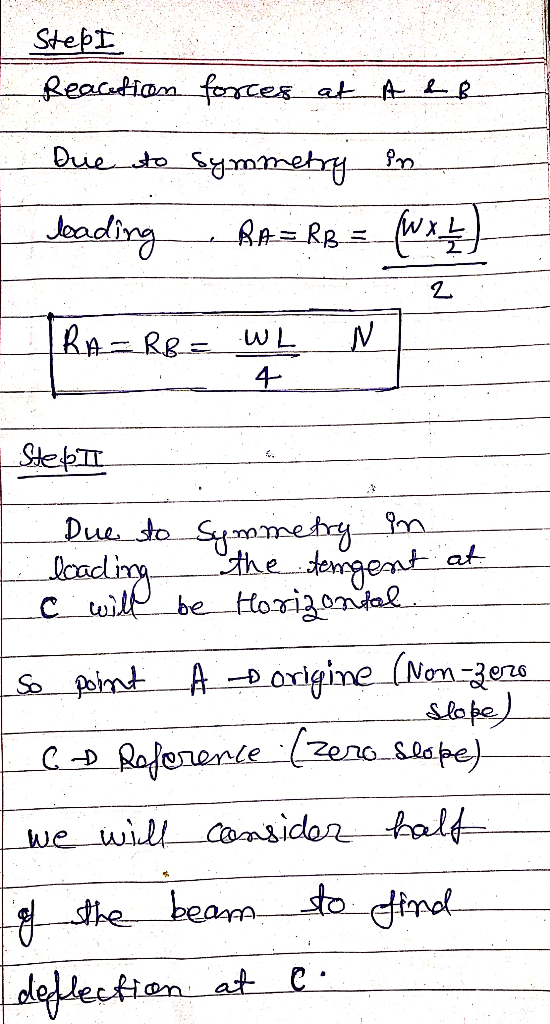
. The beam in Figure P5.26 has its central half enlarged so that the moment of inertia I is twice the "due for each end section. Determine the deflection at the center of the beam
Homework Answers


Add Answer to:
. The beam in Figure P5.26 has its central half enlarged so that
the moment of...
EMT 101- Engineering Programming Homework 3 Deflection of an I-Beam(100 %) You are to develop a program that calculates and plots the vertical deflection of a beam subjected to a force acting on it...
 EMT 101- Engineering Programming Homework 3 Deflection of an I-Beam(100 %) You are to develop a program that calculates and plots the vertical deflection of a beam subjected to a force acting on it as given in Figure 1. The I-Beam has length, L 2m with its left end fixed at the wall (no deflection at wall) The right end of the beam is applied with a vertical load force P with a vertical deflection function (3L -a) EI wherer...
Use Moment Area Theorems in the beam shown in figure 3 to determine the following: a-...
 Use Moment Area Theorems in the beam shown in figure 3 to
determine the following:
a- Deflection at C.
b- Deflection at D.
c- Slope at C.
d- Slope at D.
Use E for modulus of elasticity and I for the moment of inertia
for the whole beam.
20KN B k C pin Roller 4m 6m 4m Figure 3
Use Moment Area Theorems in the beam shown in figure 3 to
determine the following:
a- Deflection at C.
b- Deflection at D.
c- Slope at C.
d- Slope at D.
Use E for modulus of elasticity and I for the moment of inertia
for the whole beam.
20KN B k C pin Roller 4m 6m 4m Figure 3
Question 3 Use Moment Area theorems in the beam shown in Figure 3 to determine the...
 Question 3 Use Moment Area theorems in the beam shown in Figure 3 to determine the following: a-Deflection at C. b-Deflection at D. Use E for modulus of elasticity and I for moment of inertia for the whole beam. Q.3 20KN toler B → С D pin Roller 4m Figure 3 —
Review Part A The assembly consists of a cantilevered beam CB and a simply supported beam AB (Figure 1). If each beam is made of A-36 steel and has a moment of inertia about its principal axis of det...
 Review Part A The assembly consists of a cantilevered beam CB and a simply supported beam AB (Figure 1). If each beam is made of A-36 steel and has a moment of inertia about its principal axis of determine the displacement at the center D of beam BA. 136 in4 Express your answer to three significant figures and include appropriate units. AD = Value Units Submit Figure 1 of 1 15 kip Provide Feedback 8 ft 16 ft
Review Part...
Review Part A The assembly consists of a cantilevered beam CB and a simply supported beam AB (Figure 1). If each beam is made of A-36 steel and has a moment of inertia about its principal axis of determine the displacement at the center D of beam BA. 136 in4 Express your answer to three significant figures and include appropriate units. AD = Value Units Submit Figure 1 of 1 15 kip Provide Feedback 8 ft 16 ft
Review Part...
Question 3 Use Moment Area theorems in the beam shown in Figure 3 to determine the...
 Question 3 Use Moment Area theorems in the beam shown in Figure 3 to determine the following: a- Deflection at C. b- Deflection at D. - Slope at C. d- Slope at D. Use E for modulus of elasticity and I for moment of inertia for the whole beam. 0.3 CI 20kr IDEN B C pin Roller 4m Figure 3
Question 3 Use Moment Area theorems in the beam shown in Figure 3 to determine the...
 Question 3 Use Moment Area theorems in the beam shown in Figure 3 to determine the following: a- Deflection at C. b- Deflection at D. C- Slope at C. d- Slope at D. Use E for modulus of elasticity and I for moment of inertia for the whole beam. 0.3 20KN t B 2014 C D Pin Roller 4m 6m 4m figure 3
A cantilever beam of a channel section is loaded at its half-length, as shown in Figure Q2. The Young's modulus of the material is 200 GPa. Determine the deflection at the free end. [12.5 marks]...
 A cantilever beam of a channel section is loaded at its half-length, as shown in Figure Q2. The Young's modulus of the material is 200 GPa. Determine the deflection at the free end. [12.5 marks] 25 mm 25 mm 5 kN a -a 少a 6 mm 200 mm Figure Q2
A cantilever beam of a channel section is loaded at its half-length, as shown in Figure Q2. The Young's modulus of the material is 200 GPa. Determine the deflection at...
A cantilever beam of a channel section is loaded at its half-length, as shown in Figure Q2. The Young's modulus of the material is 200 GPa. Determine the deflection at the free end. [12.5 marks] 25 mm 25 mm 5 kN a -a 少a 6 mm 200 mm Figure Q2
A cantilever beam of a channel section is loaded at its half-length, as shown in Figure Q2. The Young's modulus of the material is 200 GPa. Determine the deflection at...
The simply supported beam has length L, elasticity modulus E, and cross-section with moment of inertia...
 The simply supported beam has length L, elasticity modulus E, and cross-section with moment of inertia I. A concentrated force is applied at half point, as illustrated below 1/2 1/2 o The deflection curve for the the first half of the beam is given by: 21 (2) = + (- +) Obtain the equation for the deflection curve y(x) for L/2 < x < L, where: y2(x) = (Ao + A1 x + A2 x2 + A3 x3) When solving...
1. A beam has a max moment of 45 kN-m. The cross section of the beam is shown in the figure below...
 1. A beam has a max moment of 45 kN-m. The cross section of the beam is shown in the figure below. a. State the distance of the centroid from the 2 axis. b. Calculate the area moment of inertia about the centroid. c. Calculate the maximum stress in the beam 300 mm 20 mm 185 mm 20 mm 35 mm
1. A beam has a max moment of 45 kN-m. The cross section of the beam is shown in...
1. A beam has a max moment of 45 kN-m. The cross section of the beam is shown in the figure below. a. State the distance of the centroid from the 2 axis. b. Calculate the area moment of inertia about the centroid. c. Calculate the maximum stress in the beam 300 mm 20 mm 185 mm 20 mm 35 mm
1. A beam has a max moment of 45 kN-m. The cross section of the beam is shown in...
Moment of inertia of a 200.0cm rod about its central axis is 1.25 kg.m2. Find moment...
Moment of inertia of a 200.0cm rod about its central axis is 1.25 kg.m2. Find moment of inertia of this rod about axis at 25.0 cm form one end. Moment of inertia of rod about central axis is: I= 1/12ML2
 EMT 101- Engineering Programming Homework 3 Deflection of an I-Beam(100 %) You are to develop a program that calculates and plots the vertical deflection of a beam subjected to a force acting on it as given in Figure 1. The I-Beam has length, L 2m with its left end fixed at the wall (no deflection at wall) The right end of the beam is applied with a vertical load force P with a vertical deflection function (3L -a) EI wherer...
 Use Moment Area Theorems in the beam shown in figure 3 to
determine the following:
a- Deflection at C.
b- Deflection at D.
c- Slope at C.
d- Slope at D.
Use E for modulus of elasticity and I for the moment of inertia
for the whole beam.
20KN B k C pin Roller 4m 6m 4m Figure 3
Use Moment Area Theorems in the beam shown in figure 3 to
determine the following:
a- Deflection at C.
b- Deflection at D.
c- Slope at C.
d- Slope at D.
Use E for modulus of elasticity and I for the moment of inertia
for the whole beam.
20KN B k C pin Roller 4m 6m 4m Figure 3
 Question 3 Use Moment Area theorems in the beam shown in Figure 3 to determine the following: a-Deflection at C. b-Deflection at D. Use E for modulus of elasticity and I for moment of inertia for the whole beam. Q.3 20KN toler B → С D pin Roller 4m Figure 3 —
 Review Part A The assembly consists of a cantilevered beam CB and a simply supported beam AB (Figure 1). If each beam is made of A-36 steel and has a moment of inertia about its principal axis of determine the displacement at the center D of beam BA. 136 in4 Express your answer to three significant figures and include appropriate units. AD = Value Units Submit Figure 1 of 1 15 kip Provide Feedback 8 ft 16 ft
Review Part...
Review Part A The assembly consists of a cantilevered beam CB and a simply supported beam AB (Figure 1). If each beam is made of A-36 steel and has a moment of inertia about its principal axis of determine the displacement at the center D of beam BA. 136 in4 Express your answer to three significant figures and include appropriate units. AD = Value Units Submit Figure 1 of 1 15 kip Provide Feedback 8 ft 16 ft
Review Part...
 Question 3 Use Moment Area theorems in the beam shown in Figure 3 to determine the following: a- Deflection at C. b- Deflection at D. - Slope at C. d- Slope at D. Use E for modulus of elasticity and I for moment of inertia for the whole beam. 0.3 CI 20kr IDEN B C pin Roller 4m Figure 3
 Question 3 Use Moment Area theorems in the beam shown in Figure 3 to determine the following: a- Deflection at C. b- Deflection at D. C- Slope at C. d- Slope at D. Use E for modulus of elasticity and I for moment of inertia for the whole beam. 0.3 20KN t B 2014 C D Pin Roller 4m 6m 4m figure 3
 A cantilever beam of a channel section is loaded at its half-length, as shown in Figure Q2. The Young's modulus of the material is 200 GPa. Determine the deflection at the free end. [12.5 marks] 25 mm 25 mm 5 kN a -a 少a 6 mm 200 mm Figure Q2
A cantilever beam of a channel section is loaded at its half-length, as shown in Figure Q2. The Young's modulus of the material is 200 GPa. Determine the deflection at...
A cantilever beam of a channel section is loaded at its half-length, as shown in Figure Q2. The Young's modulus of the material is 200 GPa. Determine the deflection at the free end. [12.5 marks] 25 mm 25 mm 5 kN a -a 少a 6 mm 200 mm Figure Q2
A cantilever beam of a channel section is loaded at its half-length, as shown in Figure Q2. The Young's modulus of the material is 200 GPa. Determine the deflection at...
 The simply supported beam has length L, elasticity modulus E, and cross-section with moment of inertia I. A concentrated force is applied at half point, as illustrated below 1/2 1/2 o The deflection curve for the the first half of the beam is given by: 21 (2) = + (- +) Obtain the equation for the deflection curve y(x) for L/2 < x < L, where: y2(x) = (Ao + A1 x + A2 x2 + A3 x3) When solving...
 1. A beam has a max moment of 45 kN-m. The cross section of the beam is shown in the figure below. a. State the distance of the centroid from the 2 axis. b. Calculate the area moment of inertia about the centroid. c. Calculate the maximum stress in the beam 300 mm 20 mm 185 mm 20 mm 35 mm
1. A beam has a max moment of 45 kN-m. The cross section of the beam is shown in...
1. A beam has a max moment of 45 kN-m. The cross section of the beam is shown in the figure below. a. State the distance of the centroid from the 2 axis. b. Calculate the area moment of inertia about the centroid. c. Calculate the maximum stress in the beam 300 mm 20 mm 185 mm 20 mm 35 mm
1. A beam has a max moment of 45 kN-m. The cross section of the beam is shown in...
Most questions answered within 3 hours.
-
Where is the error in this code sequence?
String s1 = "Hello";
String s2 = "ello";...
asked 10 months ago -
Financial data for Joel de Paris, Inc., for last year
follow:
Joel de Paris, Inc.
Balance...
asked 10 months ago -
Consider this reaction:
Al2(SO4)3 (aq)+ BaCl3
(aq) Al2Cl6 (aq)- +
3BaSO4(s) . What is the...
asked 10 months ago -
Suppose that Savneet is considering increasing her
recent random sample from 20 car rentals to 40...
asked 10 months ago -
Trucks arrive at an unloading terminal at an average rate of 120
per hour.
Trucks arrive...
asked 10 months ago -
Why are methanol and ethanol completely soluble in water while
octanol is not very little soluble....
asked 10 months ago -
A facilities manager at a university reads in a research report
that the mean amount of...
asked 10 months ago -
When the CuSO4 is rehydrated by adding water to the anhydrous
compound, is this an endothermic...
asked 10 months ago -
A ray of sunlight is passing from diamond into crown glass; the
angle of incidence is...
asked 10 months ago -
A block of mass 0.249 kg is placed on top of a light, vertical
spring of...
asked 10 months ago -
how do the kidneys compensate in the presences of acidosis
a) trigger hyperventilate
b) reserve acid...
asked 10 months ago -
Question 501 pts
The rental rate of capital to the firm increases. Which of the
following...
asked 10 months ago