
Homework Answers
The output is one command for the Chiller. The lights can be triggered using the same command.
It will be treated as high to run, low to stop, as nothing else is mentioned.
The inputs which can change the state of the Chiller are:
1. Four sensor inputs which trigger the Chiller to turn on when temperature exceeds 50F
2. On/Off switch
3. Outgoing water temperature sensor input: Turn off chiller when temperature falls below 45F for 4 minutes
4. Freeze control to turn off chiller at 40F
We shall look at these points one by one.
1: This is fairly straight forward logic. Since any of the sensors can turn on the Chiller, they should be connected in parallel. Since the logic command Logic would be:

2. The Start commands from the switch can also start the chiller, so they should be connected in parallel with the Sensor commands. Modified logic:

We will look at the connection for the Stop switch a little later.
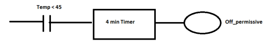
3. It is stated that when the outgoing water temperature is < 45F for 4 min, the Chiller is turned off. Let us draw the logic for this step alone. We will connect it to the Final run command eventually.
4. When outgoing water temperature is lower than 40F, the Failsafer logic should turn off the chiller. Failsafe logic is:

Let us now talk about the final logic for the Run command. For the case when started by the Sensor logic, temperature begins to fall and when it falls below 50F, the sensor output goes to 0. Hence the output of this logic needs to be latched so that the Run command stays high till temperature falls below 45F.
Hence intermediate logic:

We now need to add the conditions for stopping the Chiller in series with this latched command. The conditions are: Temperature logic (Temp below 45F for 4 min), Failsafe logic and Stop button at Chiller or SCADA. Add the inverted outputs generated above:

It is now seen that all conditions mentioned in the problem are satisfied.
Final ladder diagram showing all rungs together:

Footnote: It was assumed that the start/stop switch has different contacts for Start & Stop. If that is not the case, the switch status can be used to generate start/stop command by this logic:
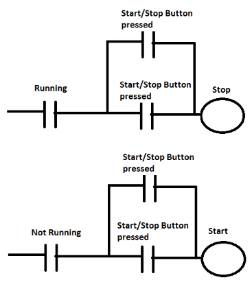
Running and Not Running here are status of the Chiller.
If this is the case, the "Start" and "Stop" shown here have to be used in the final Run logic in place of the "Start switch" & "Stop switch" from the switch shown in the original logic.
Add Answer to:
Use a ladder diagram please!
Control circuit, ladder diagram, and sequence of operations: 1. The chiller...
Lab 3 word p develop a ladder diagram from a EGN 4023 the objective of this...
 Lab 3 word p develop a ladder diagram from a EGN 4023 the objective of this practical exercise is to introduce to using interlocking and safety operation techniques. Equipment " Computer with installed software to control and program the PLC Process Application: Water Tank Level The process turning a discharge pump on or off. The modes of operation are to be programmed as follows: by shown in the Figure below is to be used to control the level of water...
I need help to write a nice introduction for experiment 6 please ( no hands write ) typing Thank you HEAT TREATMENT OF STEELS EXPERIMENT 6 EXPERIMENT 6 HEAT TREATMENT OF STEELS THEORY The Ef...
 I need help to write a nice introduction for experiment 6
please ( no hands write ) typing
Thank you
HEAT TREATMENT OF STEELS EXPERIMENT 6 EXPERIMENT 6 HEAT TREATMENT OF STEELS THEORY The Effect of Cooling Rate One of the most convenient methods for controlling the properties of a given steel, i.e., a steel whose composition is already fixed, consists of austenizing the steel and ten cooling to room temperature at some predetermined rate. A variation of cooling rates...
I need help to write a nice introduction for experiment 6
please ( no hands write ) typing
Thank you
HEAT TREATMENT OF STEELS EXPERIMENT 6 EXPERIMENT 6 HEAT TREATMENT OF STEELS THEORY The Effect of Cooling Rate One of the most convenient methods for controlling the properties of a given steel, i.e., a steel whose composition is already fixed, consists of austenizing the steel and ten cooling to room temperature at some predetermined rate. A variation of cooling rates...
 Lab 3 word p develop a ladder diagram from a EGN 4023 the objective of this practical exercise is to introduce to using interlocking and safety operation techniques. Equipment " Computer with installed software to control and program the PLC Process Application: Water Tank Level The process turning a discharge pump on or off. The modes of operation are to be programmed as follows: by shown in the Figure below is to be used to control the level of water...
 I need help to write a nice introduction for experiment 6
please ( no hands write ) typing
Thank you
HEAT TREATMENT OF STEELS EXPERIMENT 6 EXPERIMENT 6 HEAT TREATMENT OF STEELS THEORY The Effect of Cooling Rate One of the most convenient methods for controlling the properties of a given steel, i.e., a steel whose composition is already fixed, consists of austenizing the steel and ten cooling to room temperature at some predetermined rate. A variation of cooling rates...
I need help to write a nice introduction for experiment 6
please ( no hands write ) typing
Thank you
HEAT TREATMENT OF STEELS EXPERIMENT 6 EXPERIMENT 6 HEAT TREATMENT OF STEELS THEORY The Effect of Cooling Rate One of the most convenient methods for controlling the properties of a given steel, i.e., a steel whose composition is already fixed, consists of austenizing the steel and ten cooling to room temperature at some predetermined rate. A variation of cooling rates...
Most questions answered within 3 hours.
-
Where is the error in this code sequence?
String s1 = "Hello";
String s2 = "ello";...
asked 10 months ago -
Financial data for Joel de Paris, Inc., for last year
follow:
Joel de Paris, Inc.
Balance...
asked 10 months ago -
Consider this reaction:
Al2(SO4)3 (aq)+ BaCl3
(aq) Al2Cl6 (aq)- +
3BaSO4(s) . What is the...
asked 10 months ago -
Suppose that Savneet is considering increasing her
recent random sample from 20 car rentals to 40...
asked 10 months ago -
Trucks arrive at an unloading terminal at an average rate of 120
per hour.
Trucks arrive...
asked 10 months ago -
Why are methanol and ethanol completely soluble in water while
octanol is not very little soluble....
asked 10 months ago -
A facilities manager at a university reads in a research report
that the mean amount of...
asked 10 months ago -
When the CuSO4 is rehydrated by adding water to the anhydrous
compound, is this an endothermic...
asked 10 months ago -
A ray of sunlight is passing from diamond into crown glass; the
angle of incidence is...
asked 10 months ago -
A block of mass 0.249 kg is placed on top of a light, vertical
spring of...
asked 10 months ago -
how do the kidneys compensate in the presences of acidosis
a) trigger hyperventilate
b) reserve acid...
asked 10 months ago -
Question 501 pts
The rental rate of capital to the firm increases. Which of the
following...
asked 10 months ago