


Homework Answers


Add Answer to:
For the circuit shown in the figure (ε-3.50 V, R-5.00 Ω), calculate the following quantities. 12,0...
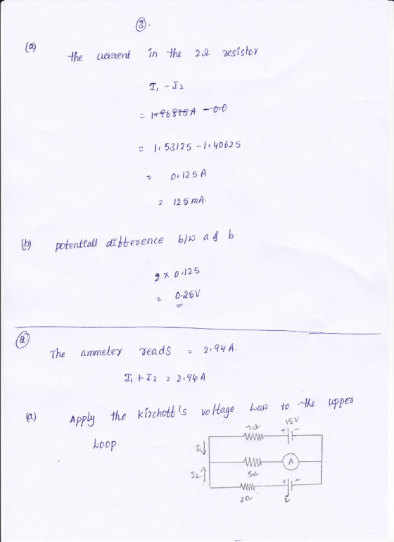
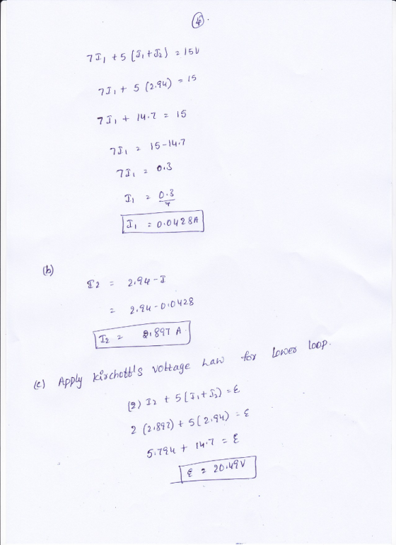
The ammeter shown in the figure below reads 2.92 A. Find 1112, and ε 2 15.0...
 The ammeter shown in the figure below reads 2.92 A. Find 1112, and ε 2 15.0 V 7.00 Ω 5.00 Ω 2.00 Ω +1- Need Help?Read It Watch It
The ammeter shown in the figure below reads 2.48 A. Find the following. (a) I1 =...
 The ammeter shown in the
figure below reads 2.48 A. Find the following. (a) I1 = Incorrect:
Your answer is incorrect. Consider applying Kirchhoff's voltage
rule to the upper loop. A (b) I2 = A (c) e m f = V
The ammeter shown in the figure below reads 2.48 A. Find the following. 15.0 V 7.00 Ω 5.00 Ω +1,- 2.00 Ω (a) 11 5.52 Consider applying Kirchhoff's voltage rule to the upper loop. A (b) I2 - (c)...
The ammeter shown in the
figure below reads 2.48 A. Find the following. (a) I1 = Incorrect:
Your answer is incorrect. Consider applying Kirchhoff's voltage
rule to the upper loop. A (b) I2 = A (c) e m f = V
The ammeter shown in the figure below reads 2.48 A. Find the following. 15.0 V 7.00 Ω 5.00 Ω +1,- 2.00 Ω (a) 11 5.52 Consider applying Kirchhoff's voltage rule to the upper loop. A (b) I2 - (c)...
For the circuit shown in the figure, calculate the following. (Assume ε = 8.40 V and R = 5.94 Ω.)
 For the circuit shown in the figure, calculate the following. (Assume ε = 8.40 V and R = 5.94 Ω.) (a) the current in the 2.00-12 resistor (Enter the magnitude.) (b) the potential difference between points a and b, ΔV = Vb - Va
The ammeter shown in the figure registers a current of 2 Ampere. Calculate the value of...
 The ammeter shown in the figure registers a current of 2 Ampere. Calculate the value of E.
A. 20.25 V
B. 12.1 V
C. 12V
D. 18.5 V
E. 24 V
F. 12.6
G. 6.5 V
H. 10.5 V7.00 Ω 15.0V και 5.00 Ω -- A 14 ε 2.00 Ω -,
The ammeter shown in the figure registers a current of 2 Ampere. Calculate the value of E.
A. 20.25 V
B. 12.1 V
C. 12V
D. 18.5 V
E. 24 V
F. 12.6
G. 6.5 V
H. 10.5 V7.00 Ω 15.0V και 5.00 Ω -- A 14 ε 2.00 Ω -,
What are the expected readings of the following in the figure below? (R-8.40 Ω, AV-670 V)...
 What are the expected readings of the following in the figure below? (R-8.40 Ω, AV-670 V) 10.0 Ω R 4.50 V (a) ideal ammeter mA (b) ideal voltmeter
What are the expected readings of the following in the figure below? (R = 8.60 Ω,...
 What are the expected readings of the following in the figure
below? (R = 8.60 Ω, ΔV = 5.90 V)
(a) ideal ammeter
(b) ideal voltmeter
What are the expected readings of the following in the figure
below? (R = 8.60 Ω, ΔV = 5.90 V)
(a) ideal ammeter
(b) ideal voltmeter
For the circuit shown in Fig. 6, calculate:(a) the current in the 2.00−Ω resistor.(b) the potential...
 For the circuit shown in Fig. 6, calculate:(a) the current in
the 2.00−Ω resistor.(b) the potential difference between points a
and b.
Assume that the components on Fig. 7 have the following
values:V1 = 10.0 V , V2 = 15.0 V , R1 = 5.0 Ω, R1 = 5.00 Ω, R2 =
10.0 Ω, R3 = 15.0 Ω, R4 = 20.0 Ω. (a) Find the current trough each
branch of the circuit. (b) Find the power dissipated in each
circuit...
For the circuit shown in Fig. 6, calculate:(a) the current in
the 2.00−Ω resistor.(b) the potential difference between points a
and b.
Assume that the components on Fig. 7 have the following
values:V1 = 10.0 V , V2 = 15.0 V , R1 = 5.0 Ω, R1 = 5.00 Ω, R2 =
10.0 Ω, R3 = 15.0 Ω, R4 = 20.0 Ω. (a) Find the current trough each
branch of the circuit. (b) Find the power dissipated in each
circuit...
The ammeter shown in the figure below reads 1.86 A. Find I1, I2, and E I1...
 The ammeter shown in the figure below reads 1.86 A. Find I1, I2, and E I1 А I2 A V 15.0 V 7.00 5.00 W + 2.00
for the circuit in the following figure, both meters are idealized.please break it down the circuit,...
 for the circuit in the following figure, both meters are
idealized.please break it down the circuit, and answer questions a
and b.
For the circuit shown in the following figure both meters are idealized, the battery has no appreciable internal resistance, and the ammeter reads 1.37 A. (Let R1-52.0 Ω, R2-27.0 Ω, and R3-R4-17 Ω·) (a) What does the voltmeter read? (b) what is the emf ε of the battery? R3 Ri R4 10.012 35.0 Ω a. 256 V b.465...
for the circuit in the following figure, both meters are
idealized.please break it down the circuit, and answer questions a
and b.
For the circuit shown in the following figure both meters are idealized, the battery has no appreciable internal resistance, and the ammeter reads 1.37 A. (Let R1-52.0 Ω, R2-27.0 Ω, and R3-R4-17 Ω·) (a) What does the voltmeter read? (b) what is the emf ε of the battery? R3 Ri R4 10.012 35.0 Ω a. 256 V b.465...
 The ammeter shown in the figure below reads 2.92 A. Find 1112, and ε 2 15.0 V 7.00 Ω 5.00 Ω 2.00 Ω +1- Need Help?Read It Watch It
 The ammeter shown in the
figure below reads 2.48 A. Find the following. (a) I1 = Incorrect:
Your answer is incorrect. Consider applying Kirchhoff's voltage
rule to the upper loop. A (b) I2 = A (c) e m f = V
The ammeter shown in the figure below reads 2.48 A. Find the following. 15.0 V 7.00 Ω 5.00 Ω +1,- 2.00 Ω (a) 11 5.52 Consider applying Kirchhoff's voltage rule to the upper loop. A (b) I2 - (c)...
The ammeter shown in the
figure below reads 2.48 A. Find the following. (a) I1 = Incorrect:
Your answer is incorrect. Consider applying Kirchhoff's voltage
rule to the upper loop. A (b) I2 = A (c) e m f = V
The ammeter shown in the figure below reads 2.48 A. Find the following. 15.0 V 7.00 Ω 5.00 Ω +1,- 2.00 Ω (a) 11 5.52 Consider applying Kirchhoff's voltage rule to the upper loop. A (b) I2 - (c)...
 The ammeter shown in the figure registers a current of 2 Ampere. Calculate the value of E.
A. 20.25 V
B. 12.1 V
C. 12V
D. 18.5 V
E. 24 V
F. 12.6
G. 6.5 V
H. 10.5 V7.00 Ω 15.0V και 5.00 Ω -- A 14 ε 2.00 Ω -,
The ammeter shown in the figure registers a current of 2 Ampere. Calculate the value of E.
A. 20.25 V
B. 12.1 V
C. 12V
D. 18.5 V
E. 24 V
F. 12.6
G. 6.5 V
H. 10.5 V7.00 Ω 15.0V και 5.00 Ω -- A 14 ε 2.00 Ω -,
 What are the expected readings of the following in the figure below? (R-8.40 Ω, AV-670 V) 10.0 Ω R 4.50 V (a) ideal ammeter mA (b) ideal voltmeter
 What are the expected readings of the following in the figure
below? (R = 8.60 Ω, ΔV = 5.90 V)
(a) ideal ammeter
(b) ideal voltmeter
What are the expected readings of the following in the figure
below? (R = 8.60 Ω, ΔV = 5.90 V)
(a) ideal ammeter
(b) ideal voltmeter
 For the circuit shown in Fig. 6, calculate:(a) the current in
the 2.00−Ω resistor.(b) the potential difference between points a
and b.
Assume that the components on Fig. 7 have the following
values:V1 = 10.0 V , V2 = 15.0 V , R1 = 5.0 Ω, R1 = 5.00 Ω, R2 =
10.0 Ω, R3 = 15.0 Ω, R4 = 20.0 Ω. (a) Find the current trough each
branch of the circuit. (b) Find the power dissipated in each
circuit...
For the circuit shown in Fig. 6, calculate:(a) the current in
the 2.00−Ω resistor.(b) the potential difference between points a
and b.
Assume that the components on Fig. 7 have the following
values:V1 = 10.0 V , V2 = 15.0 V , R1 = 5.0 Ω, R1 = 5.00 Ω, R2 =
10.0 Ω, R3 = 15.0 Ω, R4 = 20.0 Ω. (a) Find the current trough each
branch of the circuit. (b) Find the power dissipated in each
circuit...
 The ammeter shown in the figure below reads 1.86 A. Find I1, I2, and E I1 А I2 A V 15.0 V 7.00 5.00 W + 2.00
 for the circuit in the following figure, both meters are
idealized.please break it down the circuit, and answer questions a
and b.
For the circuit shown in the following figure both meters are idealized, the battery has no appreciable internal resistance, and the ammeter reads 1.37 A. (Let R1-52.0 Ω, R2-27.0 Ω, and R3-R4-17 Ω·) (a) What does the voltmeter read? (b) what is the emf ε of the battery? R3 Ri R4 10.012 35.0 Ω a. 256 V b.465...
for the circuit in the following figure, both meters are
idealized.please break it down the circuit, and answer questions a
and b.
For the circuit shown in the following figure both meters are idealized, the battery has no appreciable internal resistance, and the ammeter reads 1.37 A. (Let R1-52.0 Ω, R2-27.0 Ω, and R3-R4-17 Ω·) (a) What does the voltmeter read? (b) what is the emf ε of the battery? R3 Ri R4 10.012 35.0 Ω a. 256 V b.465...
Most questions answered within 3 hours.
-
Where is the error in this code sequence?
String s1 = "Hello";
String s2 = "ello";...
asked 11 months ago -
Financial data for Joel de Paris, Inc., for last year
follow:
Joel de Paris, Inc.
Balance...
asked 11 months ago -
Consider this reaction:
Al2(SO4)3 (aq)+ BaCl3
(aq) Al2Cl6 (aq)- +
3BaSO4(s) . What is the...
asked 11 months ago -
Suppose that Savneet is considering increasing her
recent random sample from 20 car rentals to 40...
asked 11 months ago -
Trucks arrive at an unloading terminal at an average rate of 120
per hour.
Trucks arrive...
asked 11 months ago -
Why are methanol and ethanol completely soluble in water while
octanol is not very little soluble....
asked 11 months ago -
A facilities manager at a university reads in a research report
that the mean amount of...
asked 11 months ago -
When the CuSO4 is rehydrated by adding water to the anhydrous
compound, is this an endothermic...
asked 11 months ago -
A ray of sunlight is passing from diamond into crown glass; the
angle of incidence is...
asked 11 months ago -
A block of mass 0.249 kg is placed on top of a light, vertical
spring of...
asked 11 months ago -
how do the kidneys compensate in the presences of acidosis
a) trigger hyperventilate
b) reserve acid...
asked 11 months ago -
Question 501 pts
The rental rate of capital to the firm increases. Which of the
following...
asked 11 months ago