

*State diagrams are the same just had to upload it in two pictures, sorry.
Homework Answers

Add Answer to:
*State diagrams are the same just had to upload it in two
pictures, sorry.
The state...
Design a state machine that implements the following description: Let’s design a simple controller for an...
Design a state machine that implements the following description: Let’s design a simple controller for an elevator. The elevator can be at one of two floors: first or second. There is a button that controls the elevator (one input), and it has two values: up or down. Also, there are two lights in the elevator that indicate the current floor: blue for first, and yellow for second. At each time step, the controller checks the current floor and current input...
Please help Q15. A watch can display one of four items: Time, Alarm, Stopwatch or Date, controlled by two signals Q1 and Q0 (00 time, 01 alarm, 10 stopwatch, 11date). Assume Q1 and Q0 control an N...
 Please help
Q15. A watch can display one of four items: Time, Alarm, Stopwatch or Date, controlled by two signals Q1 and Q0 (00 time, 01 alarm, 10 stopwatch, 11date). Assume Q1 and Q0 control an N-bit MUX that passes the correct register to the display. Pressing a button B (sets B-1) sequences the display to the next item, releasing the button resets B-0 and the display remains stable. For example, if the current displayed item is the date the...
Please help
Q15. A watch can display one of four items: Time, Alarm, Stopwatch or Date, controlled by two signals Q1 and Q0 (00 time, 01 alarm, 10 stopwatch, 11date). Assume Q1 and Q0 control an N-bit MUX that passes the correct register to the display. Pressing a button B (sets B-1) sequences the display to the next item, releasing the button resets B-0 and the display remains stable. For example, if the current displayed item is the date the...
Not just fill the next states with 0 and 1. Please show and explain how to...
 Not just fill the next states with 0 and 1. Please show and
explain how to get to the next state encoder from the diagram.
Thanks!
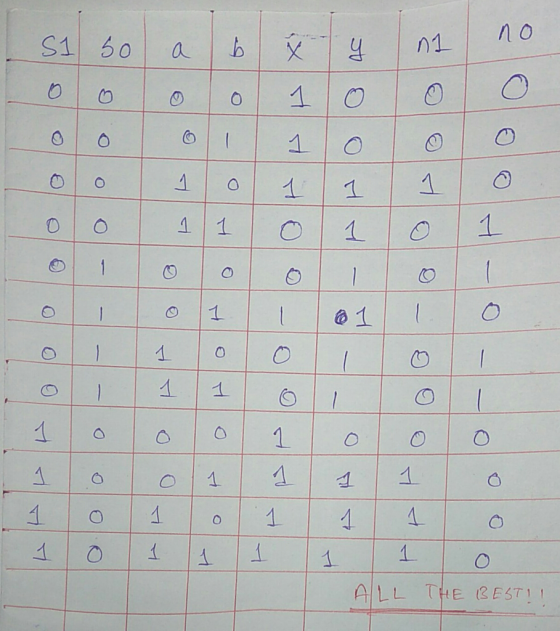
12. (a) (8 points) Given the state diagram below, create a truth table for the next state encoder. Start AB 01 AB (b) (6 points) Use the truth table you built to produce SOP logic expressions for the two state variables SiSo 00 01 11 10 S1So 00 01 11 10 N, AB 01...
Not just fill the next states with 0 and 1. Please show and
explain how to get to the next state encoder from the diagram.
Thanks!
12. (a) (8 points) Given the state diagram below, create a truth table for the next state encoder. Start AB 01 AB (b) (6 points) Use the truth table you built to produce SOP logic expressions for the two state variables SiSo 00 01 11 10 S1So 00 01 11 10 N, AB 01...
Design the following finite state machine (FSM). It has two 1-bit inputs (in1 and in2) and...
Design the following finite state machine (FSM). It has two 1-bit inputs (in1 and in2) and two 1-bit outputs (out1 and out2). The first output (out1) bit should be equal to one if, on both of the last two cycles, in1 and in2 were EQUAL to each other; otherwise, out1 should equal zero. The second output (out2) should be equal to 1 if, on the last cycle, in1 and in2 were NOT EQUAL to each other; otherwise, out2 should equal...
Digital Logic Fundamentals. Need help with this assignment!!! Want to make sure I'm on the right ...
 Digital Logic Fundamentals. Need help with this
assignment!!!
Want to make sure I'm on the right track with the truth table
and K-MAPS.
Also I'd like to know how to design the LOGISIM circuit.
Thank you.
igital Logic Fundamentals An Excess-3 code exists for the following reason: The primary advantage of excess-3 coding over non-biased coding is that a decimal number can be nines' complemented (for subtraction) as easily as a binary number can be ones' complemented: just by inverting...
Digital Logic Fundamentals. Need help with this
assignment!!!
Want to make sure I'm on the right track with the truth table
and K-MAPS.
Also I'd like to know how to design the LOGISIM circuit.
Thank you.
igital Logic Fundamentals An Excess-3 code exists for the following reason: The primary advantage of excess-3 coding over non-biased coding is that a decimal number can be nines' complemented (for subtraction) as easily as a binary number can be ones' complemented: just by inverting...
Q3. Figure 3 below shows the initial state diagram for a two input (X2, Xi), single output (Z) control system. Design a...
 Q3. Figure 3 below shows the initial state diagram for a two input (X2, Xi), single output (Z) control system. Design a Moore asynchronous logic solution addressing the following steps A flow table a) [5 marks] b) A merged flow table (explaining why merging was used, and showing the re-numbered merged states) and the revised merged state diagram [8 marks] Assign state variables, and generate an excitation table, marking transitions from unstable to stable states, making statements regarding the presence...
A combination circuit is specified by the following Boolean functions listed below. h(a, b, c) = b,c' + a'c Implement the circuit with a 3x8 decoder. Provide truth table and drawing the l...
 A combination circuit is specified by the following Boolean functions listed below. h(a, b, c) = b,c' + a'c Implement the circuit with a 3x8 decoder. Provide truth table and drawing the logic/circuit diagram. Use the block diagram for the decoder provided in Figure A4 in supplements. Please label the inputs and outputs clearly. Note: use single 3x8 decoder Question 2 (15 points] A priority encoder is an encoder circuit that includes the Truth Table of a priority function. The...
P6 (15 points): The FSM state diagram below has two inputs x1 and xo In addition,...
 P6 (15 points): The FSM state diagram below has two inputs x1 and xo In addition, it has two DFFS, three 4-to-1 MUXes, a single XOR gate, a single AND gate, and a single output bit Z. Answer the following questions about this FSM. o/0 10/0 RESET A 61/0 C 9/0 01/0 1/0 o1/0 6/0 A: Is this a Moore FSM or a Mealy FSM? B: The state encodings are A-00, B-01, C-10, and D=11. Write a state- assigned table...
Can someone please show me a circuit diagram so i can see how to construct this...
 Can someone please show me a circuit diagram so i can see how to
construct this on a bread board i am id 6 yhanks in advance
EEET-2251: Course & Projoct Guide 2018 EEET-2251: Cousc &Projoct Guide 2018 affic Light Controller A single switch must set your HC74 based state machine to the initial state (the U state This lab will get you to design a simple controller for a pedestrian crossing based on synchronous digital logic. You will master...
Can someone please show me a circuit diagram so i can see how to
construct this on a bread board i am id 6 yhanks in advance
EEET-2251: Course & Projoct Guide 2018 EEET-2251: Cousc &Projoct Guide 2018 affic Light Controller A single switch must set your HC74 based state machine to the initial state (the U state This lab will get you to design a simple controller for a pedestrian crossing based on synchronous digital logic. You will master...
Its logic design my sequence is 127605 i need help with all this pages please and thank you
 Its logic design
my sequence is 127605
i need help with all this pages please and thank you
27 60 Experiment 4 Six-State Up-Down Counter 1 Objective To become familiar with the design procedures of a counter, which are applicable to the design of other synchronous sequential circuits. 2 Problem description A six-state up-down counter is to be designed. Three flip-flops with outputs Q2,Qi and Qo are required in the design. As shown in Figure 1, the counter is initialized...
Its logic design
my sequence is 127605
i need help with all this pages please and thank you
27 60 Experiment 4 Six-State Up-Down Counter 1 Objective To become familiar with the design procedures of a counter, which are applicable to the design of other synchronous sequential circuits. 2 Problem description A six-state up-down counter is to be designed. Three flip-flops with outputs Q2,Qi and Qo are required in the design. As shown in Figure 1, the counter is initialized...
 Please help
Q15. A watch can display one of four items: Time, Alarm, Stopwatch or Date, controlled by two signals Q1 and Q0 (00 time, 01 alarm, 10 stopwatch, 11date). Assume Q1 and Q0 control an N-bit MUX that passes the correct register to the display. Pressing a button B (sets B-1) sequences the display to the next item, releasing the button resets B-0 and the display remains stable. For example, if the current displayed item is the date the...
Please help
Q15. A watch can display one of four items: Time, Alarm, Stopwatch or Date, controlled by two signals Q1 and Q0 (00 time, 01 alarm, 10 stopwatch, 11date). Assume Q1 and Q0 control an N-bit MUX that passes the correct register to the display. Pressing a button B (sets B-1) sequences the display to the next item, releasing the button resets B-0 and the display remains stable. For example, if the current displayed item is the date the...
 Not just fill the next states with 0 and 1. Please show and
explain how to get to the next state encoder from the diagram.
Thanks!
12. (a) (8 points) Given the state diagram below, create a truth table for the next state encoder. Start AB 01 AB (b) (6 points) Use the truth table you built to produce SOP logic expressions for the two state variables SiSo 00 01 11 10 S1So 00 01 11 10 N, AB 01...
Not just fill the next states with 0 and 1. Please show and
explain how to get to the next state encoder from the diagram.
Thanks!
12. (a) (8 points) Given the state diagram below, create a truth table for the next state encoder. Start AB 01 AB (b) (6 points) Use the truth table you built to produce SOP logic expressions for the two state variables SiSo 00 01 11 10 S1So 00 01 11 10 N, AB 01...
 Digital Logic Fundamentals. Need help with this
assignment!!!
Want to make sure I'm on the right track with the truth table
and K-MAPS.
Also I'd like to know how to design the LOGISIM circuit.
Thank you.
igital Logic Fundamentals An Excess-3 code exists for the following reason: The primary advantage of excess-3 coding over non-biased coding is that a decimal number can be nines' complemented (for subtraction) as easily as a binary number can be ones' complemented: just by inverting...
Digital Logic Fundamentals. Need help with this
assignment!!!
Want to make sure I'm on the right track with the truth table
and K-MAPS.
Also I'd like to know how to design the LOGISIM circuit.
Thank you.
igital Logic Fundamentals An Excess-3 code exists for the following reason: The primary advantage of excess-3 coding over non-biased coding is that a decimal number can be nines' complemented (for subtraction) as easily as a binary number can be ones' complemented: just by inverting...
 Q3. Figure 3 below shows the initial state diagram for a two input (X2, Xi), single output (Z) control system. Design a Moore asynchronous logic solution addressing the following steps A flow table a) [5 marks] b) A merged flow table (explaining why merging was used, and showing the re-numbered merged states) and the revised merged state diagram [8 marks] Assign state variables, and generate an excitation table, marking transitions from unstable to stable states, making statements regarding the presence...
 A combination circuit is specified by the following Boolean functions listed below. h(a, b, c) = b,c' + a'c Implement the circuit with a 3x8 decoder. Provide truth table and drawing the logic/circuit diagram. Use the block diagram for the decoder provided in Figure A4 in supplements. Please label the inputs and outputs clearly. Note: use single 3x8 decoder Question 2 (15 points] A priority encoder is an encoder circuit that includes the Truth Table of a priority function. The...
 P6 (15 points): The FSM state diagram below has two inputs x1 and xo In addition, it has two DFFS, three 4-to-1 MUXes, a single XOR gate, a single AND gate, and a single output bit Z. Answer the following questions about this FSM. o/0 10/0 RESET A 61/0 C 9/0 01/0 1/0 o1/0 6/0 A: Is this a Moore FSM or a Mealy FSM? B: The state encodings are A-00, B-01, C-10, and D=11. Write a state- assigned table...
 Can someone please show me a circuit diagram so i can see how to
construct this on a bread board i am id 6 yhanks in advance
EEET-2251: Course & Projoct Guide 2018 EEET-2251: Cousc &Projoct Guide 2018 affic Light Controller A single switch must set your HC74 based state machine to the initial state (the U state This lab will get you to design a simple controller for a pedestrian crossing based on synchronous digital logic. You will master...
Can someone please show me a circuit diagram so i can see how to
construct this on a bread board i am id 6 yhanks in advance
EEET-2251: Course & Projoct Guide 2018 EEET-2251: Cousc &Projoct Guide 2018 affic Light Controller A single switch must set your HC74 based state machine to the initial state (the U state This lab will get you to design a simple controller for a pedestrian crossing based on synchronous digital logic. You will master...
 Its logic design
my sequence is 127605
i need help with all this pages please and thank you
27 60 Experiment 4 Six-State Up-Down Counter 1 Objective To become familiar with the design procedures of a counter, which are applicable to the design of other synchronous sequential circuits. 2 Problem description A six-state up-down counter is to be designed. Three flip-flops with outputs Q2,Qi and Qo are required in the design. As shown in Figure 1, the counter is initialized...
Its logic design
my sequence is 127605
i need help with all this pages please and thank you
27 60 Experiment 4 Six-State Up-Down Counter 1 Objective To become familiar with the design procedures of a counter, which are applicable to the design of other synchronous sequential circuits. 2 Problem description A six-state up-down counter is to be designed. Three flip-flops with outputs Q2,Qi and Qo are required in the design. As shown in Figure 1, the counter is initialized...
Most questions answered within 3 hours.
-
Where is the error in this code sequence?
String s1 = "Hello";
String s2 = "ello";...
asked 10 months ago -
Financial data for Joel de Paris, Inc., for last year
follow:
Joel de Paris, Inc.
Balance...
asked 10 months ago -
Consider this reaction:
Al2(SO4)3 (aq)+ BaCl3
(aq) Al2Cl6 (aq)- +
3BaSO4(s) . What is the...
asked 10 months ago -
Suppose that Savneet is considering increasing her
recent random sample from 20 car rentals to 40...
asked 10 months ago -
Trucks arrive at an unloading terminal at an average rate of 120
per hour.
Trucks arrive...
asked 10 months ago -
Why are methanol and ethanol completely soluble in water while
octanol is not very little soluble....
asked 10 months ago -
A facilities manager at a university reads in a research report
that the mean amount of...
asked 10 months ago -
When the CuSO4 is rehydrated by adding water to the anhydrous
compound, is this an endothermic...
asked 10 months ago -
A ray of sunlight is passing from diamond into crown glass; the
angle of incidence is...
asked 10 months ago -
A block of mass 0.249 kg is placed on top of a light, vertical
spring of...
asked 10 months ago -
how do the kidneys compensate in the presences of acidosis
a) trigger hyperventilate
b) reserve acid...
asked 10 months ago -
Question 501 pts
The rental rate of capital to the firm increases. Which of the
following...
asked 10 months ago