a five bus system
The equipment ratings for a five bus system are given as 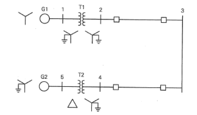
Generator G1: 50 MVA, 12 kV, Xd ’’=X2=0.20, X0= 0.10 per unit
Generator G2: 100 MVA, 15 kV, Xd ’’=0.2, X2=0.23, X0= 0.10 per unit
Transformer T1: 50 MVA, 10 kV (Y)/138 kV (Y), X=0.10 per unit
Transformer T1: 100 MVA, 15 kV (∆)/138 kV (Y), X=0.10 per unit
Each 138 kV line: X1=40 Ohms, X0=100 ohms
(1) Draw out the zero-, positive-, and negative- sequence reactance diagrams for the original system using a 100-MVA, 15-kV base. Neglect the ∆/Y transformer phase shift;
(2) For a fault with zero impedance at bus 1, determine the Thevenin equivalent circuit for each sequence network as viewed from faulted bus. Neglect the ∆/Y transformer phase shift and prefault voltage is 1 p.u. ;
(3) Determine the sub-transient fault current for the fault in (2).
Homework Answers
Request Answer!
We need at least 10 more requests to produce the answer.
0 / 10 have requested this problem solution
The more requests, the faster the answer.
Transformer TI : 50 MVA, 10 kV Y/138 kV Y, X=0.10 per unit; Transformer T2: 100 MVA, 15 kV D/138 kV Y, X-0.10 per unit; Each 138-kV line: X1-400 A three-phase short circuit occurs at bus 5,...
 Transformer TI : 50 MVA, 10 kV Y/138 kV Y, X=0.10 per unit; Transformer T2: 100 MVA, 15 kV D/138 kV Y, X-0.10 per unit; Each 138-kV line: X1-400 A three-phase short circuit occurs at bus 5, where the prefault voltage is 15 kV. Prefault load current is neglected. (a)Draw the positive-sequence reactance diagram in per-unit on a 100-MVA, 15-kV base in the zone of generator G2. Determine: (b) the The'venin equivalent at the fault, (c) the subtransient fault current...
Four-bus power system shown in Fig. 1 are as follows: Generator G1: 200 MVA, 7.2 kv,...
 Four-bus power system shown in Fig. 1 are as follows: Generator G1: 200 MVA, 7.2 kv, X -0.15 p.u Generator G2: 250 MVA, 9.6 kV, X-0.12 p.u Generator G3: 500 MVA, 10 kV, X-0.25 p.u Transformer T1:200 MVA, 7.2 Δ /132 Y kV, X= 0.05 p.u Transformer T2: 250 MVA, 9.6 Δ /132 Y kV, X =0.15 p.u Transformer T3: 500 MVA, 10 Δ /132 Y kV, x-0.1 p.u Each 132-kV line:X,-10 Ω 1- A three-phase short circuit occurs at...
2. A single-line diagram of the power system considered is shown in Figure P2a, where negative-...
 2. A single-line diagram of the power system considered is shown in Figure P2a, where negative- and zero-sequence reactances are also given. The neutrals of the generator and A-Y transformers are solidly grounded. The motor neutral is grounded through a reactance Xn = 0.05 per unit on the motor base. The per-unit zero-, positive and negative-sequence networks on a 100-MVA is shown in Figure P26, 13.8-kV base in the zone of the generator. a. Reduce the sequence networks to their...
QUESTION 4. A single-line diagram of a power system is shown in Figure Q3 below, where...
 QUESTION 4. A single-line diagram of a power system is shown in Figure Q3 below, where negative and zero-sequence reactances are also given. The neutrals of the generator and A-Y transformers are solidly grounded. The motor neutral is grounded through a reactance X.=0.05 per unit on the motor base. Prefault voltage is VF1.05<Oº per unit whereas prefault load current is zero. Take A-Y transformer phase shifts into consideration. M Line tool X, - X2 - 200 100 MVA X =...
A single line diagram of a power system is shown in Fig. 2. The system data with equipment ratings and assumed sequence reactances are given the following table. The neutrals of the generator and A-Y...
 A single line diagram of a power system is shown in Fig. 2. The system data with equipment ratings and assumed sequence reactances are given the following table. The neutrals of the generator and A-Y transformers are solidly grounded. The motor neutral is grounded through a reactance Xn 0.05 per unit on the motor base. Assume that Pre-fault voltage is takin as VF-1.0 ,0° per unit and Pre- fault load current and Δ-Y transformer phase shift are neglected In the...
Assuming there is a FAULT at BUS 3, Determine the thevenin equivalent of each series network...
 Assuming there is a FAULT at BUS 3, Determine the thevenin
equivalent of each series network as viewed from the fault bus.
Given:
-Prefault voltage is 1.0 per unit
-Prefault load currents and delta-wye transformer phase shifts
are neglected
Synchronous generators G1 1000 MVA 15 kVX"-X2 0.18, Xo 0.07 per unit G2 1000 MVA 15 kV X: X, = 0.20, X,-0.10 per unit G3 500 MVA 13.8 kV X: X,-0.15, X,-0.05 per unit G4 750 MVA 13.8 kV X,-0.30, X,-0.40,...
Assuming there is a FAULT at BUS 3, Determine the thevenin
equivalent of each series network as viewed from the fault bus.
Given:
-Prefault voltage is 1.0 per unit
-Prefault load currents and delta-wye transformer phase shifts
are neglected
Synchronous generators G1 1000 MVA 15 kVX"-X2 0.18, Xo 0.07 per unit G2 1000 MVA 15 kV X: X, = 0.20, X,-0.10 per unit G3 500 MVA 13.8 kV X: X,-0.15, X,-0.05 per unit G4 750 MVA 13.8 kV X,-0.30, X,-0.40,...
Q3: (15 Points) Equi below are given as follows: pment ratings and per-unit reactances for the sy...
 Q3: (15 Points) Equi below are given as follows: pment ratings and per-unit reactances for the system shown in circuit 2 4 T1 TL12 T2b G1 G2 TL13 TL23 0.03 j0.03 Synchronous Generators: G1 100 MVA 25 kV G2 100 MVA 3.8 kV Transformers: T1 100 MVA 25/230 kV T2 100 MVA 13.8 /230 kV X1=X2= 0.2 X0-0.05 X1-X2-0.2 X0 0.05 X1 = X2-X0 = 0.05 Transmission lines: TL12 100 MVA TL13 100 MVA TL23 100 MVA X0 0.3 XO...
Figure 1 Single line diagram b2 b3 b1 b4 grid Τι 13 A power system single line diagram is shown...
 Figure 1 Single line diagram b2 b3 b1 b4 grid Τι 13 A power system single line diagram is shown in Figure 1. The single line diagram shows a synchronous generator G connected to a large 50 Hz grid via its unit transformer T and a network of three transmission lines. Relevant details of the grid, transformer, generator and overhead lines are provided in Tables I,II,II & IV respectively. A double line to ground fault occurs at bus 3 Questions....
Bus A Bus B R1 T1 line 1 20% 80% line 2 T2 R2 110 kV 11 kV The fault is located at point F, which...
 Bus A Bus B R1 T1 line 1 20% 80% line 2 T2 R2 110 kV 11 kV The fault is located at point F, which is 20% of the total line 2 length from Bus B Fault MVA 1524.20471 Three-phase fault level in MVA at bus A SPFL (kA) 8 MVA1 MVA2 X1 (96) X2 (96) R1 (2) R2 (Q) z' (Q) Zo (2) Rf (Q) Single phase to ground fault level (kA) at bus A Transformer 1 MVA...
The following are the answers: Autumn 2013 T1 G1 5 kV 50 MVA 5/20 kV 50...
 The following are the answers:
Autumn 2013 T1 G1 5 kV 50 MVA 5/20 kV 50 MVA 20 kV 50 MVA X 0.1 p.u Figure A13 In the system shown, per-unit series equivalent impedances are shown for each element. Before a balanced 3-phase fault occurs in the location shown, the pre-fault current is at its rated value at 90 % lagging power factor flowing from generator G1 The generator is operating at full voltage. How much current in kA is...
The following are the answers:
Autumn 2013 T1 G1 5 kV 50 MVA 5/20 kV 50 MVA 20 kV 50 MVA X 0.1 p.u Figure A13 In the system shown, per-unit series equivalent impedances are shown for each element. Before a balanced 3-phase fault occurs in the location shown, the pre-fault current is at its rated value at 90 % lagging power factor flowing from generator G1 The generator is operating at full voltage. How much current in kA is...
 Transformer TI : 50 MVA, 10 kV Y/138 kV Y, X=0.10 per unit; Transformer T2: 100 MVA, 15 kV D/138 kV Y, X-0.10 per unit; Each 138-kV line: X1-400 A three-phase short circuit occurs at bus 5, where the prefault voltage is 15 kV. Prefault load current is neglected. (a)Draw the positive-sequence reactance diagram in per-unit on a 100-MVA, 15-kV base in the zone of generator G2. Determine: (b) the The'venin equivalent at the fault, (c) the subtransient fault current...
 Four-bus power system shown in Fig. 1 are as follows: Generator G1: 200 MVA, 7.2 kv, X -0.15 p.u Generator G2: 250 MVA, 9.6 kV, X-0.12 p.u Generator G3: 500 MVA, 10 kV, X-0.25 p.u Transformer T1:200 MVA, 7.2 Δ /132 Y kV, X= 0.05 p.u Transformer T2: 250 MVA, 9.6 Δ /132 Y kV, X =0.15 p.u Transformer T3: 500 MVA, 10 Δ /132 Y kV, x-0.1 p.u Each 132-kV line:X,-10 Ω 1- A three-phase short circuit occurs at...
 2. A single-line diagram of the power system considered is shown in Figure P2a, where negative- and zero-sequence reactances are also given. The neutrals of the generator and A-Y transformers are solidly grounded. The motor neutral is grounded through a reactance Xn = 0.05 per unit on the motor base. The per-unit zero-, positive and negative-sequence networks on a 100-MVA is shown in Figure P26, 13.8-kV base in the zone of the generator. a. Reduce the sequence networks to their...
 QUESTION 4. A single-line diagram of a power system is shown in Figure Q3 below, where negative and zero-sequence reactances are also given. The neutrals of the generator and A-Y transformers are solidly grounded. The motor neutral is grounded through a reactance X.=0.05 per unit on the motor base. Prefault voltage is VF1.05<Oº per unit whereas prefault load current is zero. Take A-Y transformer phase shifts into consideration. M Line tool X, - X2 - 200 100 MVA X =...
 A single line diagram of a power system is shown in Fig. 2. The system data with equipment ratings and assumed sequence reactances are given the following table. The neutrals of the generator and A-Y transformers are solidly grounded. The motor neutral is grounded through a reactance Xn 0.05 per unit on the motor base. Assume that Pre-fault voltage is takin as VF-1.0 ,0° per unit and Pre- fault load current and Δ-Y transformer phase shift are neglected In the...
 Assuming there is a FAULT at BUS 3, Determine the thevenin
equivalent of each series network as viewed from the fault bus.
Given:
-Prefault voltage is 1.0 per unit
-Prefault load currents and delta-wye transformer phase shifts
are neglected
Synchronous generators G1 1000 MVA 15 kVX"-X2 0.18, Xo 0.07 per unit G2 1000 MVA 15 kV X: X, = 0.20, X,-0.10 per unit G3 500 MVA 13.8 kV X: X,-0.15, X,-0.05 per unit G4 750 MVA 13.8 kV X,-0.30, X,-0.40,...
Assuming there is a FAULT at BUS 3, Determine the thevenin
equivalent of each series network as viewed from the fault bus.
Given:
-Prefault voltage is 1.0 per unit
-Prefault load currents and delta-wye transformer phase shifts
are neglected
Synchronous generators G1 1000 MVA 15 kVX"-X2 0.18, Xo 0.07 per unit G2 1000 MVA 15 kV X: X, = 0.20, X,-0.10 per unit G3 500 MVA 13.8 kV X: X,-0.15, X,-0.05 per unit G4 750 MVA 13.8 kV X,-0.30, X,-0.40,...
 Q3: (15 Points) Equi below are given as follows: pment ratings and per-unit reactances for the system shown in circuit 2 4 T1 TL12 T2b G1 G2 TL13 TL23 0.03 j0.03 Synchronous Generators: G1 100 MVA 25 kV G2 100 MVA 3.8 kV Transformers: T1 100 MVA 25/230 kV T2 100 MVA 13.8 /230 kV X1=X2= 0.2 X0-0.05 X1-X2-0.2 X0 0.05 X1 = X2-X0 = 0.05 Transmission lines: TL12 100 MVA TL13 100 MVA TL23 100 MVA X0 0.3 XO...
 Figure 1 Single line diagram b2 b3 b1 b4 grid Τι 13 A power system single line diagram is shown in Figure 1. The single line diagram shows a synchronous generator G connected to a large 50 Hz grid via its unit transformer T and a network of three transmission lines. Relevant details of the grid, transformer, generator and overhead lines are provided in Tables I,II,II & IV respectively. A double line to ground fault occurs at bus 3 Questions....
 Bus A Bus B R1 T1 line 1 20% 80% line 2 T2 R2 110 kV 11 kV The fault is located at point F, which is 20% of the total line 2 length from Bus B Fault MVA 1524.20471 Three-phase fault level in MVA at bus A SPFL (kA) 8 MVA1 MVA2 X1 (96) X2 (96) R1 (2) R2 (Q) z' (Q) Zo (2) Rf (Q) Single phase to ground fault level (kA) at bus A Transformer 1 MVA...
 The following are the answers:
Autumn 2013 T1 G1 5 kV 50 MVA 5/20 kV 50 MVA 20 kV 50 MVA X 0.1 p.u Figure A13 In the system shown, per-unit series equivalent impedances are shown for each element. Before a balanced 3-phase fault occurs in the location shown, the pre-fault current is at its rated value at 90 % lagging power factor flowing from generator G1 The generator is operating at full voltage. How much current in kA is...
The following are the answers:
Autumn 2013 T1 G1 5 kV 50 MVA 5/20 kV 50 MVA 20 kV 50 MVA X 0.1 p.u Figure A13 In the system shown, per-unit series equivalent impedances are shown for each element. Before a balanced 3-phase fault occurs in the location shown, the pre-fault current is at its rated value at 90 % lagging power factor flowing from generator G1 The generator is operating at full voltage. How much current in kA is...
Most questions answered within 3 hours.
-
Where is the error in this code sequence?
String s1 = "Hello";
String s2 = "ello";...
asked 11 months ago -
Financial data for Joel de Paris, Inc., for last year
follow:
Joel de Paris, Inc.
Balance...
asked 11 months ago -
Consider this reaction:
Al2(SO4)3 (aq)+ BaCl3
(aq) Al2Cl6 (aq)- +
3BaSO4(s) . What is the...
asked 11 months ago -
Suppose that Savneet is considering increasing her
recent random sample from 20 car rentals to 40...
asked 11 months ago -
Trucks arrive at an unloading terminal at an average rate of 120
per hour.
Trucks arrive...
asked 11 months ago -
Why are methanol and ethanol completely soluble in water while
octanol is not very little soluble....
asked 11 months ago -
A facilities manager at a university reads in a research report
that the mean amount of...
asked 11 months ago -
When the CuSO4 is rehydrated by adding water to the anhydrous
compound, is this an endothermic...
asked 11 months ago -
A ray of sunlight is passing from diamond into crown glass; the
angle of incidence is...
asked 11 months ago -
A block of mass 0.249 kg is placed on top of a light, vertical
spring of...
asked 11 months ago -
how do the kidneys compensate in the presences of acidosis
a) trigger hyperventilate
b) reserve acid...
asked 11 months ago -
Question 501 pts
The rental rate of capital to the firm increases. Which of the
following...
asked 11 months ago