Part C - Saturation of a summing op amp circuit
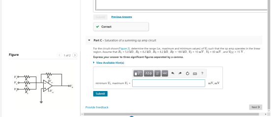
For the circuit shown(Figure 2), determine the range (i.e., maximum and minimum values) of V1V1 such that the op amp operates in the linear region. Assume that R1 = 5.0 kΩ , R2 = 8.2 kΩ , R3 = 8.2 kΩ , RF = 180 kΩ , V2 = 10 mV, V3 = 60 mV , and VCC = 15 V .
Express your answer to three significant figures separated by a comma.
Homework Answers


Add Answer to:
Part C - Saturation of a summing op amp circuit
For the circuit shown(Figure 2), determine...
Learning Goal: To analyze op amps that sum different input voltages. Before proceeding, review summing op...
 Learning Goal: To analyze op amps that sum different input voltages. Before proceeding, review summing op amp circuits and the ideal op amp assumptions. Figure 1 of 1 Review Part A - Calculating the output voltage of a summing op amp circuit For the circuit shown(Figure 1). determine V, when R1 = 3.4 kN, R2 = 5.0 kN. R3 = 7.0 kN Rp = 100 kn. Vi = 20 mV, V = 50 mV V3 = 280 mV and Voc...
Ch 5 Analysis of Ideal Op Amp Circuits 1 of 11> Part B Ideal op amp...
 Ch 5 Analysis of Ideal Op Amp Circuits 1 of 11> Part B Ideal op amp circuits with a voltage source: part 2 Learning Goal: For the circuit shown (Figure 1), determine the range (i.e., maximum and minimum values) of V so that the op amp operates in the linear region. Assume that R1-5 ? . R2-1 kN. R3-60 ? , and V,-15 V To analyze circuits that contain op amps using the ideal op amp assumptions. Express your answer...
For the Op Amp circuit shown, if the inputs v1 = 5 volts, and v2 = 3 volts
 For the Op Amp circuit shown, if the inputs v1 = 5 volts, and v2 = 3 volts, and resistances R1 = R2 =10 KΩ and RF = 5kΩ , then the output out will be _______ volts. This circuit is called a _______ OP Amp circuit. The name indicates the application of the circuit. The Op Amp provides _______ output impedance.
5. (10 points) The op amp in the precision rectifier circuit shown is ideal with output...
 5. (10 points) The op amp in the precision rectifier circuit shown is ideal with output saturation levels of = 14 V. Assume that when conducting the diode exhibits a constant voltage drop of 0.7 V, R1 = R2 = R3 =1 k2, and R4 = R5 = 2 k22. Find Vout (in V) when Vs = -2 V? Vout(Vs = -2) = -15V VEE LM348N LM348N 15V VCC
Vial Ri W 2. Find Vout = f(V1,R's). This is an inverting summing op amp circuit....
 Vial Ri W 2. Find Vout = f(V1,R's). This is an inverting summing op amp circuit. ve I, R3 Virtual eart summing poht summing pourt
1)What is the output voltage V0 if op-amp is ideal? R1= 2 KΩ, R2=8 KΩ, R3=3.2...
 1)What is the output
voltage V0 if op-amp is ideal?
R1= 2 KΩ, R2=8 KΩ, R3=3.2 KΩ, R4=6 KΩ, R5=19
KΩ, R6=4.6 KΩ, RL=9.6 KΩ, V1=1V, I2=0.5 mA and V3=2.5 V.
2) for the same circuit, R1= 2 KΩ R2=8
KΩ, R3=3.6 KΩ, R4=6 KΩ, R5=16.9 KΩ, R6=15 KΩ, RL=10 KΩ, V1=1V,
I2=0.5mA and V3=2V. What is the input impedance as
seen by source V3?
+ | R1 ہی ہے۔ ۸۸۸ ة -(1+ R5 | + ابرها -
1)What is the output
voltage V0 if op-amp is ideal?
R1= 2 KΩ, R2=8 KΩ, R3=3.2 KΩ, R4=6 KΩ, R5=19
KΩ, R6=4.6 KΩ, RL=9.6 KΩ, V1=1V, I2=0.5 mA and V3=2.5 V.
2) for the same circuit, R1= 2 KΩ R2=8
KΩ, R3=3.6 KΩ, R4=6 KΩ, R5=16.9 KΩ, R6=15 KΩ, RL=10 KΩ, V1=1V,
I2=0.5mA and V3=2V. What is the input impedance as
seen by source V3?
+ | R1 ہی ہے۔ ۸۸۸ ة -(1+ R5 | + ابرها -
Q2. For the op-amp circuit as shown below, given that RS = 49.5 k, RL =...
 Q2. For the op-amp circuit as shown below, given that RS = 49.5 k, RL = 12 k 2, R1 = 10 kO, R2 = 9 ㏀, R3 = 7.5 ko, R4 = 5 ㏀R5 = 2.2 k2 Ry vo Ry Ri Rs (a) Determine the voltage gain G1-vo1/vs: Submit Answer Tries o/5 (b) Determine the voltage gain G2-vo/vs: Submit Answer Tries o/5 Q3. For the op-amp circuit shown below, find the value of VO, where R1 = 20 Ω,...
The op amp in the circuit in (Figure 1) is ideal. Suppose R-16 kΩ Part A...
 The op amp in the circuit in (Figure 1) is ideal. Suppose R-16 kΩ Part A What op amp circuit configuration is this? O This circuit is an example of the inverting amplifier o This circuit is an example of the non-inverting amplifier Submit Request Answer ▼ Part B Find vo in terms of vs Express your answer in terms of vs 07 Figure 1 of 1 > Submit Request Answer Part C 56 kΩ Find the minimum value of...
For the following circuit, assuming the op-amp is ideal, find the current through the load (IL)...
 For the following circuit, assuming the op-amp is ideal, find the current through the load (IL) if V1=3.4V, V2=2V, R1=1.9K9, R2=7.1K2, R3=1 KO, R4=39 KO and RL=1.9K RL R4 R1 w V1 R2 R3 V2 Answer: OmA Consider the same circuit as in with Question 1, but with the following new component values: V1=3.4V, V2=6V, R1=1.9K2, R2=7.1K2, R3=1 K., R4=39 K22 and RL=1.9K2. What is the input impedance as seen by the source V1?
For the following circuit, assuming the op-amp is ideal, find the current through the load (IL)...
 For the following circuit, assuming the op-amp is ideal, find
the current through the load (IL) if V1=3.7V, V2=2V, R1=1.5KΩ,
R2=8.5KΩ, R3=1 KΩ, R4=39 KΩ and RL=2.3KΩ.
Consider the same circuit as in with Question 1, but
with the following new component values:
V1=3.7V, V2=6V, R1=1.5KΩ, R2=8.5KΩ, R3=1
KΩ, R4=39 KΩ and RL=2.3KΩ. What is the input impedance as
seen by the source V1?
RL R4 w n w n + R1 +1 V1 R2 R3 } > +1 V2
For the following circuit, assuming the op-amp is ideal, find
the current through the load (IL) if V1=3.7V, V2=2V, R1=1.5KΩ,
R2=8.5KΩ, R3=1 KΩ, R4=39 KΩ and RL=2.3KΩ.
Consider the same circuit as in with Question 1, but
with the following new component values:
V1=3.7V, V2=6V, R1=1.5KΩ, R2=8.5KΩ, R3=1
KΩ, R4=39 KΩ and RL=2.3KΩ. What is the input impedance as
seen by the source V1?
RL R4 w n w n + R1 +1 V1 R2 R3 } > +1 V2
 Learning Goal: To analyze op amps that sum different input voltages. Before proceeding, review summing op amp circuits and the ideal op amp assumptions. Figure 1 of 1 Review Part A - Calculating the output voltage of a summing op amp circuit For the circuit shown(Figure 1). determine V, when R1 = 3.4 kN, R2 = 5.0 kN. R3 = 7.0 kN Rp = 100 kn. Vi = 20 mV, V = 50 mV V3 = 280 mV and Voc...
 Ch 5 Analysis of Ideal Op Amp Circuits 1 of 11> Part B Ideal op amp circuits with a voltage source: part 2 Learning Goal: For the circuit shown (Figure 1), determine the range (i.e., maximum and minimum values) of V so that the op amp operates in the linear region. Assume that R1-5 ? . R2-1 kN. R3-60 ? , and V,-15 V To analyze circuits that contain op amps using the ideal op amp assumptions. Express your answer...
 5. (10 points) The op amp in the precision rectifier circuit shown is ideal with output saturation levels of = 14 V. Assume that when conducting the diode exhibits a constant voltage drop of 0.7 V, R1 = R2 = R3 =1 k2, and R4 = R5 = 2 k22. Find Vout (in V) when Vs = -2 V? Vout(Vs = -2) = -15V VEE LM348N LM348N 15V VCC
 Vial Ri W 2. Find Vout = f(V1,R's). This is an inverting summing op amp circuit. ve I, R3 Virtual eart summing poht summing pourt
 1)What is the output
voltage V0 if op-amp is ideal?
R1= 2 KΩ, R2=8 KΩ, R3=3.2 KΩ, R4=6 KΩ, R5=19
KΩ, R6=4.6 KΩ, RL=9.6 KΩ, V1=1V, I2=0.5 mA and V3=2.5 V.
2) for the same circuit, R1= 2 KΩ R2=8
KΩ, R3=3.6 KΩ, R4=6 KΩ, R5=16.9 KΩ, R6=15 KΩ, RL=10 KΩ, V1=1V,
I2=0.5mA and V3=2V. What is the input impedance as
seen by source V3?
+ | R1 ہی ہے۔ ۸۸۸ ة -(1+ R5 | + ابرها -
1)What is the output
voltage V0 if op-amp is ideal?
R1= 2 KΩ, R2=8 KΩ, R3=3.2 KΩ, R4=6 KΩ, R5=19
KΩ, R6=4.6 KΩ, RL=9.6 KΩ, V1=1V, I2=0.5 mA and V3=2.5 V.
2) for the same circuit, R1= 2 KΩ R2=8
KΩ, R3=3.6 KΩ, R4=6 KΩ, R5=16.9 KΩ, R6=15 KΩ, RL=10 KΩ, V1=1V,
I2=0.5mA and V3=2V. What is the input impedance as
seen by source V3?
+ | R1 ہی ہے۔ ۸۸۸ ة -(1+ R5 | + ابرها -
 Q2. For the op-amp circuit as shown below, given that RS = 49.5 k, RL = 12 k 2, R1 = 10 kO, R2 = 9 ㏀, R3 = 7.5 ko, R4 = 5 ㏀R5 = 2.2 k2 Ry vo Ry Ri Rs (a) Determine the voltage gain G1-vo1/vs: Submit Answer Tries o/5 (b) Determine the voltage gain G2-vo/vs: Submit Answer Tries o/5 Q3. For the op-amp circuit shown below, find the value of VO, where R1 = 20 Ω,...
 The op amp in the circuit in (Figure 1) is ideal. Suppose R-16 kΩ Part A What op amp circuit configuration is this? O This circuit is an example of the inverting amplifier o This circuit is an example of the non-inverting amplifier Submit Request Answer ▼ Part B Find vo in terms of vs Express your answer in terms of vs 07 Figure 1 of 1 > Submit Request Answer Part C 56 kΩ Find the minimum value of...
 For the following circuit, assuming the op-amp is ideal, find the current through the load (IL) if V1=3.4V, V2=2V, R1=1.9K9, R2=7.1K2, R3=1 KO, R4=39 KO and RL=1.9K RL R4 R1 w V1 R2 R3 V2 Answer: OmA Consider the same circuit as in with Question 1, but with the following new component values: V1=3.4V, V2=6V, R1=1.9K2, R2=7.1K2, R3=1 K., R4=39 K22 and RL=1.9K2. What is the input impedance as seen by the source V1?
 For the following circuit, assuming the op-amp is ideal, find
the current through the load (IL) if V1=3.7V, V2=2V, R1=1.5KΩ,
R2=8.5KΩ, R3=1 KΩ, R4=39 KΩ and RL=2.3KΩ.
Consider the same circuit as in with Question 1, but
with the following new component values:
V1=3.7V, V2=6V, R1=1.5KΩ, R2=8.5KΩ, R3=1
KΩ, R4=39 KΩ and RL=2.3KΩ. What is the input impedance as
seen by the source V1?
RL R4 w n w n + R1 +1 V1 R2 R3 } > +1 V2
For the following circuit, assuming the op-amp is ideal, find
the current through the load (IL) if V1=3.7V, V2=2V, R1=1.5KΩ,
R2=8.5KΩ, R3=1 KΩ, R4=39 KΩ and RL=2.3KΩ.
Consider the same circuit as in with Question 1, but
with the following new component values:
V1=3.7V, V2=6V, R1=1.5KΩ, R2=8.5KΩ, R3=1
KΩ, R4=39 KΩ and RL=2.3KΩ. What is the input impedance as
seen by the source V1?
RL R4 w n w n + R1 +1 V1 R2 R3 } > +1 V2
Most questions answered within 3 hours.
-
Where is the error in this code sequence?
String s1 = "Hello";
String s2 = "ello";...
asked 11 months ago -
Financial data for Joel de Paris, Inc., for last year
follow:
Joel de Paris, Inc.
Balance...
asked 11 months ago -
Consider this reaction:
Al2(SO4)3 (aq)+ BaCl3
(aq) Al2Cl6 (aq)- +
3BaSO4(s) . What is the...
asked 11 months ago -
Suppose that Savneet is considering increasing her
recent random sample from 20 car rentals to 40...
asked 11 months ago -
Trucks arrive at an unloading terminal at an average rate of 120
per hour.
Trucks arrive...
asked 11 months ago -
Why are methanol and ethanol completely soluble in water while
octanol is not very little soluble....
asked 11 months ago -
A facilities manager at a university reads in a research report
that the mean amount of...
asked 11 months ago -
When the CuSO4 is rehydrated by adding water to the anhydrous
compound, is this an endothermic...
asked 11 months ago -
A ray of sunlight is passing from diamond into crown glass; the
angle of incidence is...
asked 11 months ago -
A block of mass 0.249 kg is placed on top of a light, vertical
spring of...
asked 11 months ago -
how do the kidneys compensate in the presences of acidosis
a) trigger hyperventilate
b) reserve acid...
asked 11 months ago -
Question 501 pts
The rental rate of capital to the firm increases. Which of the
following...
asked 11 months ago