
Homework Answers

Add Answer to:
1. (32 points) In the circuit pictured at the right, the switch S is closed at...
1. The switch S is closed at t = 0 (assume that the battery voltage remains...
 1. The switch S is closed at t = 0 (assume that the battery
voltage remains constant at 10V and the resistance of the inductor
is negligible). Calculate the voltage across each resistor a very
long time after the switch has been closed and all currents and
voltages reached steady values. (5 points)1. The switch S is closed
at t = 0 (assume that the battery voltage remains constant at 10V
and the resistance of the inductor is negligible). Calculate...
1. The switch S is closed at t = 0 (assume that the battery
voltage remains constant at 10V and the resistance of the inductor
is negligible). Calculate the voltage across each resistor a very
long time after the switch has been closed and all currents and
voltages reached steady values. (5 points)1. The switch S is closed
at t = 0 (assume that the battery voltage remains constant at 10V
and the resistance of the inductor is negligible). Calculate...
(3) The RL circuit shown in Figure 3 has a switch that is closed att 0....
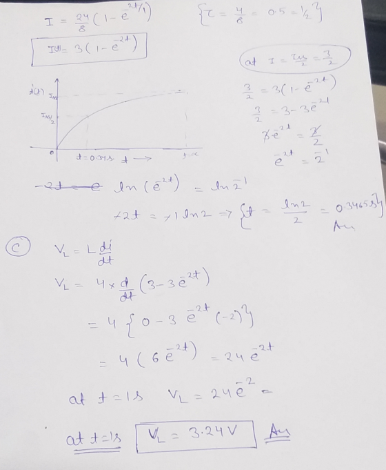
 (3) The RL circuit shown in Figure 3 has a switch that is closed att 0. Assume that the circuit has reached steady state prior to the switch closing. You are given R1 1 kQ, R2-10 kQ, R3-R4-100 k2, L 10 mH, Vs-5 V. (a) [15 pts] Calculate the steady-state inductor current before the switch is closed (b) [16 pts] Give the differential equation as an expression of the inductor current fort>0 (i.e. write the differential equation) (c) 13 pts]...
= 0 Rs=50 In the adjoining circuit, the switch, which had been closed for a sufficiently...
 = 0 Rs=50 In the adjoining circuit, the switch, which had been closed for a sufficiently long time for steady state to be reached, is opened at time t = 0. Determine the following, as a function of time: (a) The current iz(t) through the inductor, and (6) The voltage vr(t) across the 1k12 resistor. Vs= 20 V ficco Ro 1 knull 1 H elle
Rs=50 Wh. Problem 2. (8 Points) In the adjoining circuit, the switch, which had been closed...
 Rs=50 Wh. Problem 2. (8 Points) In the adjoining circuit, the switch, which had been closed for a sufficiently long time for steady state to be reached, is opened at time t = 0. Determine the following, as a function of time: (a) The current il(t) through the inductor, and (b) The voltage vr(t) across the 1k2 resistor. Vs fico) R. i kny (1) 20 V 1 H 3
4. In the circuit below, the capacitors are initially uncharged. The switch is closed at t=0....
 4. In the circuit below, the capacitors are initially uncharged. The switch is closed at t=0. 2k 22 O 9V 10 uF 20 F a. What is the time constant for this circuit? b. Sketch a plot of the current through the resistor as a function of time. Label both current and time axes with accurate numerical values. c. Sketch a plot of the charge on the 10 uF capacitor as a function of time. Label both charge and time...
In the adjoining circuit, the switch, which had been closed for a sufficiently long time for...
 In the adjoining circuit, the switch, which had been closed for
a sufficiently long time for steady state to be reached, is opened
at time t = 0. Determine the following, as a function of time:
(a) The current I L(t) through the inductor, and (b) The voltage
v R(t) across the 1k Ohm resistor.
I=0 Rs=5.12 [26) Vs= + Ro= 1 k 2 20 V 1 H 0000 vr(t)
In the adjoining circuit, the switch, which had been closed for
a sufficiently long time for steady state to be reached, is opened
at time t = 0. Determine the following, as a function of time:
(a) The current I L(t) through the inductor, and (b) The voltage
v R(t) across the 1k Ohm resistor.
I=0 Rs=5.12 [26) Vs= + Ro= 1 k 2 20 V 1 H 0000 vr(t)
1. An RL circuit comprised of one resistor and one inductor is shown in the figure...
 1. An RL circuit comprised of one resistor and one inductor is shown in the figure below. The resistor and inductor are connected to a source of emf with negligible internal resistance by a switch a. The emf for this circuit is 12.0 V. The resistance of the resistor is 0.35 12, and the inductance of the inductor is 53 mH. For the circuit below: a. Sketch the graph of current through the inductor as a function of time after...
1. An RL circuit comprised of one resistor and one inductor is shown in the figure below. The resistor and inductor...
 1. An RL circuit comprised of one resistor and one inductor is shown in the figure below. The resistor and inductor are connected to a source of emf with negligible internal resistance by a switch a. The emf for this circuit is 12.0 V. The resistance of the resistor is 0.35 , and the inductance of the inductor is 53 mH. For the circuit below: a. Sketch the graph of current through the inductor as a function of time after...
10 2 M 1. The switch S is closed at t = 0 (assume that the...
 10 2 M 1. The switch S is closed at t = 0 (assume that the battery voltage remains constant at 10V and the resistance of the inductor is negligible). Calculate the voltage across each resistor a very long time after the switch has been closed and all currents and voltages reached steady values. (5 points) 10 V 1002 000 2 H 2. A very long time after t = 0, when all currents and voltages in the circuit have...
 1. The switch S is closed at t = 0 (assume that the battery
voltage remains constant at 10V and the resistance of the inductor
is negligible). Calculate the voltage across each resistor a very
long time after the switch has been closed and all currents and
voltages reached steady values. (5 points)1. The switch S is closed
at t = 0 (assume that the battery voltage remains constant at 10V
and the resistance of the inductor is negligible). Calculate...
1. The switch S is closed at t = 0 (assume that the battery
voltage remains constant at 10V and the resistance of the inductor
is negligible). Calculate the voltage across each resistor a very
long time after the switch has been closed and all currents and
voltages reached steady values. (5 points)1. The switch S is closed
at t = 0 (assume that the battery voltage remains constant at 10V
and the resistance of the inductor is negligible). Calculate...
 (3) The RL circuit shown in Figure 3 has a switch that is closed att 0. Assume that the circuit has reached steady state prior to the switch closing. You are given R1 1 kQ, R2-10 kQ, R3-R4-100 k2, L 10 mH, Vs-5 V. (a) [15 pts] Calculate the steady-state inductor current before the switch is closed (b) [16 pts] Give the differential equation as an expression of the inductor current fort>0 (i.e. write the differential equation) (c) 13 pts]...
 = 0 Rs=50 In the adjoining circuit, the switch, which had been closed for a sufficiently long time for steady state to be reached, is opened at time t = 0. Determine the following, as a function of time: (a) The current iz(t) through the inductor, and (6) The voltage vr(t) across the 1k12 resistor. Vs= 20 V ficco Ro 1 knull 1 H elle
 Rs=50 Wh. Problem 2. (8 Points) In the adjoining circuit, the switch, which had been closed for a sufficiently long time for steady state to be reached, is opened at time t = 0. Determine the following, as a function of time: (a) The current il(t) through the inductor, and (b) The voltage vr(t) across the 1k2 resistor. Vs fico) R. i kny (1) 20 V 1 H 3
 4. In the circuit below, the capacitors are initially uncharged. The switch is closed at t=0. 2k 22 O 9V 10 uF 20 F a. What is the time constant for this circuit? b. Sketch a plot of the current through the resistor as a function of time. Label both current and time axes with accurate numerical values. c. Sketch a plot of the charge on the 10 uF capacitor as a function of time. Label both charge and time...
 In the adjoining circuit, the switch, which had been closed for
a sufficiently long time for steady state to be reached, is opened
at time t = 0. Determine the following, as a function of time:
(a) The current I L(t) through the inductor, and (b) The voltage
v R(t) across the 1k Ohm resistor.
I=0 Rs=5.12 [26) Vs= + Ro= 1 k 2 20 V 1 H 0000 vr(t)
In the adjoining circuit, the switch, which had been closed for
a sufficiently long time for steady state to be reached, is opened
at time t = 0. Determine the following, as a function of time:
(a) The current I L(t) through the inductor, and (b) The voltage
v R(t) across the 1k Ohm resistor.
I=0 Rs=5.12 [26) Vs= + Ro= 1 k 2 20 V 1 H 0000 vr(t)
 1. An RL circuit comprised of one resistor and one inductor is shown in the figure below. The resistor and inductor are connected to a source of emf with negligible internal resistance by a switch a. The emf for this circuit is 12.0 V. The resistance of the resistor is 0.35 12, and the inductance of the inductor is 53 mH. For the circuit below: a. Sketch the graph of current through the inductor as a function of time after...
 1. An RL circuit comprised of one resistor and one inductor is shown in the figure below. The resistor and inductor are connected to a source of emf with negligible internal resistance by a switch a. The emf for this circuit is 12.0 V. The resistance of the resistor is 0.35 12, and the inductance of the inductor is 53 mH. For the circuit below: a. Sketch the graph of current through the inductor as a function of time after...
 1. An RL circuit comprised of one resistor and one inductor is shown in the figure below. The resistor and inductor are connected to a source of emf with negligible internal resistance by a switch a. The emf for this circuit is 12.0 V. The resistance of the resistor is 0.35 , and the inductance of the inductor is 53 mH. For the circuit below: a. Sketch the graph of current through the inductor as a function of time after...
 10 2 M 1. The switch S is closed at t = 0 (assume that the battery voltage remains constant at 10V and the resistance of the inductor is negligible). Calculate the voltage across each resistor a very long time after the switch has been closed and all currents and voltages reached steady values. (5 points) 10 V 1002 000 2 H 2. A very long time after t = 0, when all currents and voltages in the circuit have...
Most questions answered within 3 hours.
-
Where is the error in this code sequence?
String s1 = "Hello";
String s2 = "ello";...
asked 10 months ago -
Financial data for Joel de Paris, Inc., for last year
follow:
Joel de Paris, Inc.
Balance...
asked 10 months ago -
Consider this reaction:
Al2(SO4)3 (aq)+ BaCl3
(aq) Al2Cl6 (aq)- +
3BaSO4(s) . What is the...
asked 10 months ago -
Suppose that Savneet is considering increasing her
recent random sample from 20 car rentals to 40...
asked 10 months ago -
Trucks arrive at an unloading terminal at an average rate of 120
per hour.
Trucks arrive...
asked 10 months ago -
Why are methanol and ethanol completely soluble in water while
octanol is not very little soluble....
asked 10 months ago -
A facilities manager at a university reads in a research report
that the mean amount of...
asked 10 months ago -
When the CuSO4 is rehydrated by adding water to the anhydrous
compound, is this an endothermic...
asked 10 months ago -
A ray of sunlight is passing from diamond into crown glass; the
angle of incidence is...
asked 10 months ago -
A block of mass 0.249 kg is placed on top of a light, vertical
spring of...
asked 10 months ago -
how do the kidneys compensate in the presences of acidosis
a) trigger hyperventilate
b) reserve acid...
asked 10 months ago -
Question 501 pts
The rental rate of capital to the firm increases. Which of the
following...
asked 10 months ago