
Homework Answers
please upvote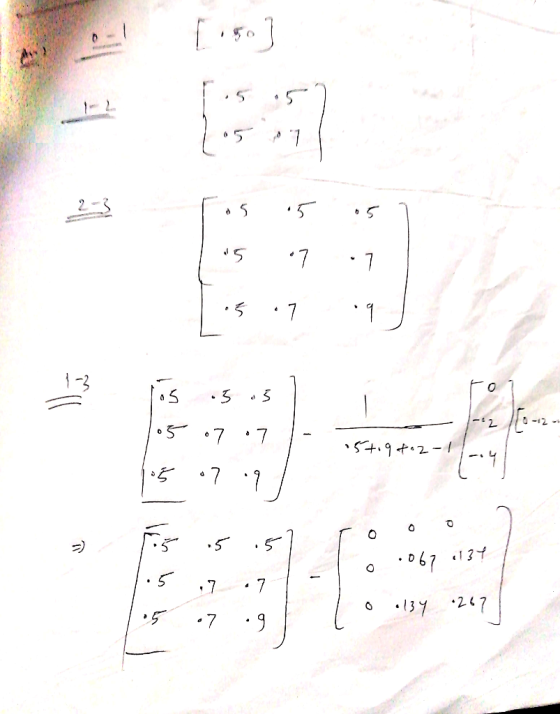

Add Answer to:
7. Fig.2. Shows a 3-bus network. Obtain the Impedance Matrix (ZBus) by following the order of...
The single-line diagram of a four-bus system and its bus impedance matrix are shown below BUS...
 The single-line diagram of a four-bus system and its bus impedance matrix are shown below BUS 2 0.25 j0.2 0.125 0.25 0.4 BUS 3 BUS 1 BUS 4 j0.1 0.1 j0.2 j0.2 ground is the reference node) 0.25 0.2 0.16 0.14 0.2 0.23 0.15 0.151 ZBUs =기0.16 0.15 0.196 0.1 0.14 0.151 0. 0.195 A solid three-phase fault occurs at bus 2 of the network. (a) Calculate the initial symmetrical RMS current in the fault. (b) Determine the voltages during...
3- The bus impedance matrix of a four-bus network with values in per unit is Z???...
3- The bus impedance matrix of a four-bus network with values in per unit is Z??? = [?0.15 ?0.08 ?0.04 ?0.07 ?0.08 ?0.15 ?0.06 ?0.09 ?0.04 ?0.06 ?0.13 ?0.05 ?0.07 ?0.09 ?0.05 ?0.12 ] Generators connected to busses 1 and 2 have their sub-transient reactances included in Zbus. Neglect pre-fault currents and find sub-transient current in pu in the fault for a three-phase fault on bus 4. Assume the voltage at fault is 1∠0 before the fault occurs. Also, find...
Consider the impedance diagram of a simple energy distribution network seen in fig. 1. The transmission...
 Consider the impedance diagram of a simple energy distribution network seen in fig. 1. The transmission lines that connect the buses have the line impedances as shown in the figure. The generators connected to buses 1 and 2 are known to be E1=1.0 pu (per unit) and E2=0.5 pu, respectively, on a 1 MV base. a) (05) Draw the admittance diagram for the system shown in fig. 1. b) (10) Obtain the bus admittance matrix Ybus for the system. c)...
Consider the 4-bus power system shown in Fig. 1. The system parameters are given below: 50 MVA, 2...
 Please show all the clearly step
Y11 ist j30 and Y44 isnt -j12.85
Consider the 4-bus power system shown in Fig. 1. The system parameters are given below: 50 MVA, 20 kV, X-2090 40 MVA, 20 kV, X-20%, X, = 5% 50 MVA, 20 kV Δ /110 kV Ý, X= 1090 50 MVA, 20 kV MI 10 kV Ý, X= 10% Xi-24.2 Ω Generator G: Motor M: Transformer T1 : Transformer T2 : Transmission line: 3 4 T2 nu)M Fig....
Please show all the clearly step
Y11 ist j30 and Y44 isnt -j12.85
Consider the 4-bus power system shown in Fig. 1. The system parameters are given below: 50 MVA, 20 kV, X-2090 40 MVA, 20 kV, X-20%, X, = 5% 50 MVA, 20 kV Δ /110 kV Ý, X= 1090 50 MVA, 20 kV MI 10 kV Ý, X= 10% Xi-24.2 Ω Generator G: Motor M: Transformer T1 : Transformer T2 : Transmission line: 3 4 T2 nu)M Fig....
QUESTION 1 1.1 The bus impedance matrix of Figure 1 is given as j0.2 5 J0.125...
 QUESTION 1 1.1 The bus impedance matrix of Figure 1 is given as j0.2 5 J0.125 0.7166006092 0589 2)|JO.60992 ј0.73190 j0.64008 j05559 30j0,6008j0.71660 0.66951 ④Ij0.58049 ј0.69659 j0.66951 j076310 j 0.25 0.4 1.25 4 1.25 Reference Between buses 1 and 4 of Figure 1 impedance Zb-j0.25 per unit is connected so that it couples through mutual impedance j0.15 per unit to the branch impedance already connected between buses 1 and 2. Modify the bus impedance matrix to include the addition of...
2. The Fig. P2.1 shows the one-line diagram of a simple four-bus system. Table P2.1 gives...
 2. The Fig. P2.1 shows the one-line diagram of a simple four-bus
system. Table P2.1
gives the line impedances identified by the buses on which these
terminate. The
shunt admittance at all the buses is assumed negligible
(a) Convert the network impedances to admittances.
(b) Obtain the bus admittance YBUS assuming that the line shown
dotted is not
connected.
(c) (i) What modifications need to be carried out in YBUS if the
dotted line is
now connected.
(ii) Obtain the...
2. The Fig. P2.1 shows the one-line diagram of a simple four-bus
system. Table P2.1
gives the line impedances identified by the buses on which these
terminate. The
shunt admittance at all the buses is assumed negligible
(a) Convert the network impedances to admittances.
(b) Obtain the bus admittance YBUS assuming that the line shown
dotted is not
connected.
(c) (i) What modifications need to be carried out in YBUS if the
dotted line is
now connected.
(ii) Obtain the...
The Fig. P2.1 shows the one-line diagram of a simple four-bus system. Table P2.1 gives the...
 The Fig. P2.1 shows the one-line diagram of a simple four-bus system. Table P2.1 gives the line impedances identified by the buses on which these terminate. The shunt admittance at all the buses is assumed negligible (a) Obtain the bus admittance Ygus assuming that the line shown dotted is not connected (b) (i) What modifications need to be carried out in「BUs If the dotted line is now connected? The impedance of the line is (0.01 +j0.1) pu (ii) obtain the...
The following figure shows the one-line diagram of a single power network which has the line...
 The following figure shows the one-line diagram of a single
power network which has the line admittances shown on the figure.
Each generator connected to buses 1 and 4 has a sub-transient
reactance of 0.25 pu. Determine for the network
a. Ybus
b. Zbus
c. The sub-transient current in per unit in a three-phase fault
on bus 3 and
d. The contributions to the fault current from line 1-3 and from
4-3
૩૦.૦૬૦-૬ ૬ . ૦૩72 , 30.23 90.0372૬ ૬૦.૦૦૩%...
The following figure shows the one-line diagram of a single
power network which has the line admittances shown on the figure.
Each generator connected to buses 1 and 4 has a sub-transient
reactance of 0.25 pu. Determine for the network
a. Ybus
b. Zbus
c. The sub-transient current in per unit in a three-phase fault
on bus 3 and
d. The contributions to the fault current from line 1-3 and from
4-3
૩૦.૦૬૦-૬ ૬ . ૦૩72 , 30.23 90.0372૬ ૬૦.૦૦૩%...
The single-line diagram of a three-phase five-bus power system is shown in Fig.1. All lines have ...
 The single-line diagram of a three-phase five-bus power system is shown in Fig.1. All lines have an impedance 0.0099+0.0990j pu. Line charging (capacitive) admittance can be neglected. 2-0.8830 30.2076 SD3-0.2+j0.1 SD3-1.7137+j0.5983 Sos-1.7355+j0.5496 Pe5 -0.5 G Qg5 -0.2 Fig. 1 a) Find the Ybus matrix of this system. b) Classify the buses in this system as slack, PV or PQ bus c) For each bus, state the given and unknown power flow variables. d) Find the net power injection (scheduled power)...
The single-line diagram of a three-phase live-bus power system is shown in Fig. 1. All lines...
 The single-line diagram of a three-phase live-bus power system is shown in Fig. 1. All lines have an impedance 0.0099 + 0.0990j pu. Line charging admittance can be neglected. a) Find the Ybus matrix of this system. b) Classify the buses in this system as slack, PV or PQ bus. c) For each bus, state the given and unknown power how variables. d) Find the net power Injection (scheduled power) for buses 2, 3, 4, and 5.
 The single-line diagram of a four-bus system and its bus impedance matrix are shown below BUS 2 0.25 j0.2 0.125 0.25 0.4 BUS 3 BUS 1 BUS 4 j0.1 0.1 j0.2 j0.2 ground is the reference node) 0.25 0.2 0.16 0.14 0.2 0.23 0.15 0.151 ZBUs =기0.16 0.15 0.196 0.1 0.14 0.151 0. 0.195 A solid three-phase fault occurs at bus 2 of the network. (a) Calculate the initial symmetrical RMS current in the fault. (b) Determine the voltages during...
 Consider the impedance diagram of a simple energy distribution network seen in fig. 1. The transmission lines that connect the buses have the line impedances as shown in the figure. The generators connected to buses 1 and 2 are known to be E1=1.0 pu (per unit) and E2=0.5 pu, respectively, on a 1 MV base. a) (05) Draw the admittance diagram for the system shown in fig. 1. b) (10) Obtain the bus admittance matrix Ybus for the system. c)...
 Please show all the clearly step
Y11 ist j30 and Y44 isnt -j12.85
Consider the 4-bus power system shown in Fig. 1. The system parameters are given below: 50 MVA, 20 kV, X-2090 40 MVA, 20 kV, X-20%, X, = 5% 50 MVA, 20 kV Δ /110 kV Ý, X= 1090 50 MVA, 20 kV MI 10 kV Ý, X= 10% Xi-24.2 Ω Generator G: Motor M: Transformer T1 : Transformer T2 : Transmission line: 3 4 T2 nu)M Fig....
Please show all the clearly step
Y11 ist j30 and Y44 isnt -j12.85
Consider the 4-bus power system shown in Fig. 1. The system parameters are given below: 50 MVA, 20 kV, X-2090 40 MVA, 20 kV, X-20%, X, = 5% 50 MVA, 20 kV Δ /110 kV Ý, X= 1090 50 MVA, 20 kV MI 10 kV Ý, X= 10% Xi-24.2 Ω Generator G: Motor M: Transformer T1 : Transformer T2 : Transmission line: 3 4 T2 nu)M Fig....
 QUESTION 1 1.1 The bus impedance matrix of Figure 1 is given as j0.2 5 J0.125 0.7166006092 0589 2)|JO.60992 ј0.73190 j0.64008 j05559 30j0,6008j0.71660 0.66951 ④Ij0.58049 ј0.69659 j0.66951 j076310 j 0.25 0.4 1.25 4 1.25 Reference Between buses 1 and 4 of Figure 1 impedance Zb-j0.25 per unit is connected so that it couples through mutual impedance j0.15 per unit to the branch impedance already connected between buses 1 and 2. Modify the bus impedance matrix to include the addition of...
 2. The Fig. P2.1 shows the one-line diagram of a simple four-bus
system. Table P2.1
gives the line impedances identified by the buses on which these
terminate. The
shunt admittance at all the buses is assumed negligible
(a) Convert the network impedances to admittances.
(b) Obtain the bus admittance YBUS assuming that the line shown
dotted is not
connected.
(c) (i) What modifications need to be carried out in YBUS if the
dotted line is
now connected.
(ii) Obtain the...
2. The Fig. P2.1 shows the one-line diagram of a simple four-bus
system. Table P2.1
gives the line impedances identified by the buses on which these
terminate. The
shunt admittance at all the buses is assumed negligible
(a) Convert the network impedances to admittances.
(b) Obtain the bus admittance YBUS assuming that the line shown
dotted is not
connected.
(c) (i) What modifications need to be carried out in YBUS if the
dotted line is
now connected.
(ii) Obtain the...
 The Fig. P2.1 shows the one-line diagram of a simple four-bus system. Table P2.1 gives the line impedances identified by the buses on which these terminate. The shunt admittance at all the buses is assumed negligible (a) Obtain the bus admittance Ygus assuming that the line shown dotted is not connected (b) (i) What modifications need to be carried out in「BUs If the dotted line is now connected? The impedance of the line is (0.01 +j0.1) pu (ii) obtain the...
 The following figure shows the one-line diagram of a single
power network which has the line admittances shown on the figure.
Each generator connected to buses 1 and 4 has a sub-transient
reactance of 0.25 pu. Determine for the network
a. Ybus
b. Zbus
c. The sub-transient current in per unit in a three-phase fault
on bus 3 and
d. The contributions to the fault current from line 1-3 and from
4-3
૩૦.૦૬૦-૬ ૬ . ૦૩72 , 30.23 90.0372૬ ૬૦.૦૦૩%...
The following figure shows the one-line diagram of a single
power network which has the line admittances shown on the figure.
Each generator connected to buses 1 and 4 has a sub-transient
reactance of 0.25 pu. Determine for the network
a. Ybus
b. Zbus
c. The sub-transient current in per unit in a three-phase fault
on bus 3 and
d. The contributions to the fault current from line 1-3 and from
4-3
૩૦.૦૬૦-૬ ૬ . ૦૩72 , 30.23 90.0372૬ ૬૦.૦૦૩%...
 The single-line diagram of a three-phase five-bus power system is shown in Fig.1. All lines have an impedance 0.0099+0.0990j pu. Line charging (capacitive) admittance can be neglected. 2-0.8830 30.2076 SD3-0.2+j0.1 SD3-1.7137+j0.5983 Sos-1.7355+j0.5496 Pe5 -0.5 G Qg5 -0.2 Fig. 1 a) Find the Ybus matrix of this system. b) Classify the buses in this system as slack, PV or PQ bus c) For each bus, state the given and unknown power flow variables. d) Find the net power injection (scheduled power)...
 The single-line diagram of a three-phase live-bus power system is shown in Fig. 1. All lines have an impedance 0.0099 + 0.0990j pu. Line charging admittance can be neglected. a) Find the Ybus matrix of this system. b) Classify the buses in this system as slack, PV or PQ bus. c) For each bus, state the given and unknown power how variables. d) Find the net power Injection (scheduled power) for buses 2, 3, 4, and 5.
Most questions answered within 3 hours.
-
Where is the error in this code sequence?
String s1 = "Hello";
String s2 = "ello";...
asked 10 months ago -
Financial data for Joel de Paris, Inc., for last year
follow:
Joel de Paris, Inc.
Balance...
asked 10 months ago -
Consider this reaction:
Al2(SO4)3 (aq)+ BaCl3
(aq) Al2Cl6 (aq)- +
3BaSO4(s) . What is the...
asked 10 months ago -
Suppose that Savneet is considering increasing her
recent random sample from 20 car rentals to 40...
asked 10 months ago -
Trucks arrive at an unloading terminal at an average rate of 120
per hour.
Trucks arrive...
asked 10 months ago -
Why are methanol and ethanol completely soluble in water while
octanol is not very little soluble....
asked 10 months ago -
A facilities manager at a university reads in a research report
that the mean amount of...
asked 10 months ago -
When the CuSO4 is rehydrated by adding water to the anhydrous
compound, is this an endothermic...
asked 10 months ago -
A ray of sunlight is passing from diamond into crown glass; the
angle of incidence is...
asked 10 months ago -
A block of mass 0.249 kg is placed on top of a light, vertical
spring of...
asked 10 months ago -
how do the kidneys compensate in the presences of acidosis
a) trigger hyperventilate
b) reserve acid...
asked 10 months ago -
Question 501 pts
The rental rate of capital to the firm increases. Which of the
following...
asked 10 months ago