
Homework Answers



Add Answer to:
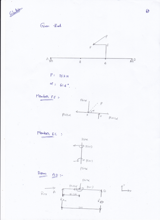
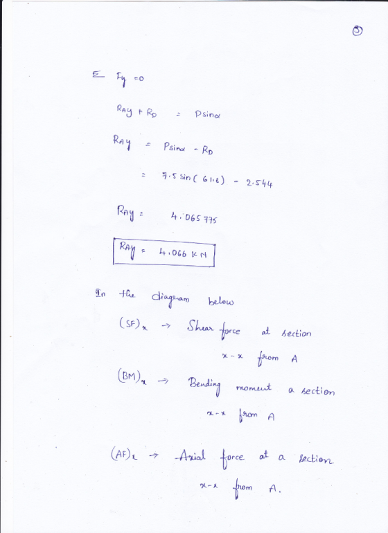
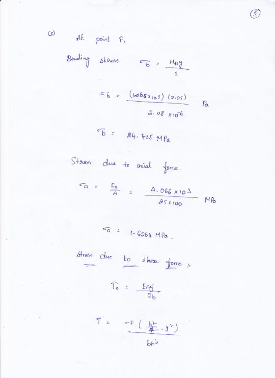
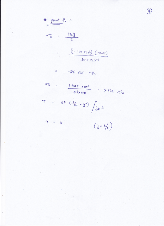
A simply supported prismatic beam is loaded with a load applied at an angle at point...
The flexural strength of a simply supported prismatic beam with depth ‘d’, width ‘b’ and span...
The flexural strength of a simply supported prismatic beam with depth ‘d’, width ‘b’ and span ‘L’ is determined using a four-point bending test. Two equal loads of value ‘P’ are placed at a distance of L/3 and 2L/3 from the support. a. Calculate the reaction forces at the supports. b. Draw the shear and moment diagrams for the beam. c. What is the location of the maximum moment on the beam? What is the value of the maximum moment?...
3. A simply-supported prismatic long beam KL is pushed upward with P 160 N at point...
 3. A simply-supported prismatic long beam KL is pushed upward with P 160 N at point N as illustrated. Please do the followings: (a) Determine the reaction forces at points K and L, respectively including their directions and magnitude and units; (b) Draw the shear diagram (V vs. x) and bending diagram is obtained step-by-step including the mathematical equations of the shear and bending moment curves, and the critical values, transition points, and slopes should be labelled clearly in numerical...
For the beam shown in the figure below a. Draw the shear and moment diagrams for this beam
 For the beam shown in the figure below a. Draw the shear and moment diagrams for this beam b. Calculate the maximum bending stress, maximum axial stress, and maximum shear stress acting on the beam cross section c. Sketch the distributions of shear stresses and bending stresses acting on the beam cross section at the locations where these stresses are maximum.
The W33 x221 steel simply supported beam is loaded with concentrated loads and uniform load as...
 The W33 x221 steel simply supported beam is loaded with
concentrated loads and uniform
load as shown with the load P= 150kip and w = 10kip/ft. For
this beam do the following;
a) Draw the shear and bending moment diagram
b) Calculate the maximum compressive and tensile stress
c) Calculate the maximum shear stress
P Р 3 ft 3 ft w 10 ft
The W33 x221 steel simply supported beam is loaded with
concentrated loads and uniform
load as shown with the load P= 150kip and w = 10kip/ft. For
this beam do the following;
a) Draw the shear and bending moment diagram
b) Calculate the maximum compressive and tensile stress
c) Calculate the maximum shear stress
P Р 3 ft 3 ft w 10 ft
Figure Q3 shows a simply supported beam carrying a point load. The beam hasa rectangular hollow...
 Figure Q3 shows a simply supported beam carrying a point load. The beam hasa rectangular hollow steel section as shown in Figure Q3. a. Calculate the second moment of area of the section about the horizontal (10 marks) centroidal axis. Calculate the maximum allowable value of the point load Wif the elastic bending (15 marks) b. stress in the beam is to be limited to 250 MPa. c. Calculate the maximum shear stress at q-q in the beam when the...
For the Wide-Flange I-beam with distributed load as in figure below calculate: 1) the shear force...
 For the Wide-Flange I-beam with distributed load as in figure below calculate: 1) the shear force V(x) and the bending moment M(x) and plot the shear and bending moment diagrams 2) the maximum bending moment MMAX For the section of the beam with Mwax calculate for each of the points A and B shown in the figure: (a) the flexural stress og (b) the principal stresses 01, 02, 03 c) the principal stress angle Upi (d) the absolute maximum shear...
(Q2) For the shown beam, a uniformly distributed load is applied across the beam length. The...
 (Q2) For the shown beam, a uniformly distributed load is applied across the beam length. The beam cross section is symmetrical. The beam length and cross-sectional dimensions are shown in figure. 40 mm B С 300 mm 10 N/m N A 40 mm 300 mm 40 mm 500 mm 1- Plot the Shear Force Distribution (with values) 2- Plot the Bending Moment Distribution (with values) 3. Determine the maximum Moment value and indicate the most critical section 4- Calculate the...
A beam may have zero shear stress at a section but may not have zero deflection;...
 A beam may have zero shear stress at a section but may not have zero deflection; Hence, bending is primarily caused by bending moment In Torsion loading a stress element in a circular rod is subject to shear state The principal plane and the plane on which the shear stresses are maximum, they make 90 degree angle between them. If the Torque on a steel circular shaft (G=80 GPa) is 13.3 kN-m and the allowable shear stress is 98 MPa,...
Problem 3 (19 points): A simply supported beam ABCD carries a uniformly distributed load, w, and...
 Problem 3 (19 points): A simply supported beam ABCD carries a uniformly distributed load, w, and a concentrated load, F, as shown in the figure. All the dimensions are given in the figure, and the weight of the beam is neglected a) Draw the free body diagram for the beam, showing all the applied and reaction forces. Find the reaction forces F=14 kN .6m b) Give the expression for the shear force, V- V(x), and the bending moment M M(x),...
Learning Goal: The beam shown (Figure 1) is supported by a pin at A and a...
 Learning Goal: The beam shown (Figure 1) is supported by a pin at A and a cable at B. Two loads P = 18 kN are applied straight down from the centerline of the bottom face. Determine the state of stress at the point shown (Figure 2) in a section 2 m from the wall. The dimensions are w = 5.4 cm , h = 12 cm, L = 0.8 m, a = 1.5 cm , and b = 4...
 3. A simply-supported prismatic long beam KL is pushed upward with P 160 N at point N as illustrated. Please do the followings: (a) Determine the reaction forces at points K and L, respectively including their directions and magnitude and units; (b) Draw the shear diagram (V vs. x) and bending diagram is obtained step-by-step including the mathematical equations of the shear and bending moment curves, and the critical values, transition points, and slopes should be labelled clearly in numerical...
 The W33 x221 steel simply supported beam is loaded with
concentrated loads and uniform
load as shown with the load P= 150kip and w = 10kip/ft. For
this beam do the following;
a) Draw the shear and bending moment diagram
b) Calculate the maximum compressive and tensile stress
c) Calculate the maximum shear stress
P Р 3 ft 3 ft w 10 ft
The W33 x221 steel simply supported beam is loaded with
concentrated loads and uniform
load as shown with the load P= 150kip and w = 10kip/ft. For
this beam do the following;
a) Draw the shear and bending moment diagram
b) Calculate the maximum compressive and tensile stress
c) Calculate the maximum shear stress
P Р 3 ft 3 ft w 10 ft
 Figure Q3 shows a simply supported beam carrying a point load. The beam hasa rectangular hollow steel section as shown in Figure Q3. a. Calculate the second moment of area of the section about the horizontal (10 marks) centroidal axis. Calculate the maximum allowable value of the point load Wif the elastic bending (15 marks) b. stress in the beam is to be limited to 250 MPa. c. Calculate the maximum shear stress at q-q in the beam when the...
 For the Wide-Flange I-beam with distributed load as in figure below calculate: 1) the shear force V(x) and the bending moment M(x) and plot the shear and bending moment diagrams 2) the maximum bending moment MMAX For the section of the beam with Mwax calculate for each of the points A and B shown in the figure: (a) the flexural stress og (b) the principal stresses 01, 02, 03 c) the principal stress angle Upi (d) the absolute maximum shear...
 (Q2) For the shown beam, a uniformly distributed load is applied across the beam length. The beam cross section is symmetrical. The beam length and cross-sectional dimensions are shown in figure. 40 mm B С 300 mm 10 N/m N A 40 mm 300 mm 40 mm 500 mm 1- Plot the Shear Force Distribution (with values) 2- Plot the Bending Moment Distribution (with values) 3. Determine the maximum Moment value and indicate the most critical section 4- Calculate the...
 A beam may have zero shear stress at a section but may not have zero deflection; Hence, bending is primarily caused by bending moment In Torsion loading a stress element in a circular rod is subject to shear state The principal plane and the plane on which the shear stresses are maximum, they make 90 degree angle between them. If the Torque on a steel circular shaft (G=80 GPa) is 13.3 kN-m and the allowable shear stress is 98 MPa,...
 Problem 3 (19 points): A simply supported beam ABCD carries a uniformly distributed load, w, and a concentrated load, F, as shown in the figure. All the dimensions are given in the figure, and the weight of the beam is neglected a) Draw the free body diagram for the beam, showing all the applied and reaction forces. Find the reaction forces F=14 kN .6m b) Give the expression for the shear force, V- V(x), and the bending moment M M(x),...
 Learning Goal: The beam shown (Figure 1) is supported by a pin at A and a cable at B. Two loads P = 18 kN are applied straight down from the centerline of the bottom face. Determine the state of stress at the point shown (Figure 2) in a section 2 m from the wall. The dimensions are w = 5.4 cm , h = 12 cm, L = 0.8 m, a = 1.5 cm , and b = 4...
Most questions answered within 3 hours.
-
Where is the error in this code sequence?
String s1 = "Hello";
String s2 = "ello";...
asked 11 months ago -
Financial data for Joel de Paris, Inc., for last year
follow:
Joel de Paris, Inc.
Balance...
asked 11 months ago -
Consider this reaction:
Al2(SO4)3 (aq)+ BaCl3
(aq) Al2Cl6 (aq)- +
3BaSO4(s) . What is the...
asked 11 months ago -
Suppose that Savneet is considering increasing her
recent random sample from 20 car rentals to 40...
asked 11 months ago -
Trucks arrive at an unloading terminal at an average rate of 120
per hour.
Trucks arrive...
asked 11 months ago -
Why are methanol and ethanol completely soluble in water while
octanol is not very little soluble....
asked 11 months ago -
A facilities manager at a university reads in a research report
that the mean amount of...
asked 11 months ago -
When the CuSO4 is rehydrated by adding water to the anhydrous
compound, is this an endothermic...
asked 11 months ago -
A ray of sunlight is passing from diamond into crown glass; the
angle of incidence is...
asked 11 months ago -
A block of mass 0.249 kg is placed on top of a light, vertical
spring of...
asked 11 months ago -
how do the kidneys compensate in the presences of acidosis
a) trigger hyperventilate
b) reserve acid...
asked 11 months ago -
Question 501 pts
The rental rate of capital to the firm increases. Which of the
following...
asked 11 months ago