
Homework Answers


Add Answer to:
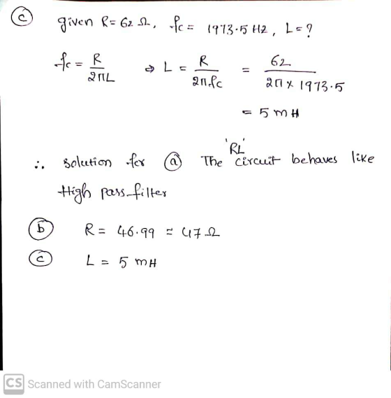
R Vin(s) - Vout(s) For the above given RL circuit, a) (10p) Please define whether it...
What kind of filter is this? Vout C W + Vin R not a filter band...
 What kind of filter is this? Vout C W + Vin R not a filter band stop high pass band pass low pass
1. The circuit below, which uses one inductor and two identical resistors, (30 pts] can be...
 1. The circuit below, which uses one inductor and two identical resistors, (30 pts] can be described as a filter. Using this circuit: a. Determine the transfer function, H(@) = Vout/Vin. b. Determine the magnitude and phase (in terms of R, L, and o) of the transfer function from part a. Now, assume R = 5022 and L = 2mH c. What is the value of the magnitude as 0 0 d. The value of the magnitude as → e....
- Vin R W Vout For the active low-pass filter above, calculate the break frequency in...
 - Vin R W Vout For the active low-pass filter above, calculate the break frequency in Hz and the low- frequency gain in dB if R1 = 47 k22, R2 = 820 k22 and C = 100 pF.
Mark with an X, the best answer for each statement below. Show your reasoning 9. EXTRA CREDIT: The ac circuit in Fig. 9(a), with the output VouT, acts as a: [2 points extra credit] a. 12 F Vin (t) 6...
 Mark with an X, the best answer for each statement below. Show your reasoning 9. EXTRA CREDIT: The ac circuit in Fig. 9(a), with the output VouT, acts as a: [2 points extra credit] a. 12 F Vin (t) 6 S2 low-pass filter (see Table Vourl t) band-pass filter (see Table) band-stop filter (see Table) high-pass filter (see Table) 12 H iv. V. Fig. 9 (a) _ None of the above Table: Filter Definitions Pass Stop Low-Pass b. For the...
R 1800 с 220 pF 220 pF VIN VOUT R 1800 kn R1 12 ko R2...
 R 1800 с 220 pF 220 pF VIN VOUT R 1800 kn R1 12 ko R2 10 k Figure A-6. 14. Look at the circuit that's shown in Figure A-6. This circuit is a A. two-pole high-pass filter. B. two pole low-pass filter. C. two-pole passive filter. D. three-pole active filter.
Question 1: For the circuit below: R С MH + + Vin L Vout Given that:...
 Question 1: For the circuit below: R С MH + + Vin L Vout Given that: R= 151, ZŁ= 35 2 and Zc = Answer the following questions: a. Calculate the input Admittance Yin(s) =1/ Zin(s) b. Consider Yin(s) as the system's transfer function, calculate the following: 1. Wp: 2. Bw: 3. W1 and W2: 4. Hm: C. Draw the second order response on the graph below (show W1, W2, HM values): |(200) DRESSE
Problem 5: (20 points) Given the following circuit VIN L Vout R a) Write the loop...
 Problem 5: (20 points) Given the following circuit VIN L Vout R a) Write the loop equation for the circuit, and then find the transfer function Vout(s) H(S) = Express H(s) so that the coefficient of the s in the denominator is 1. Vin(s) b) If Vin(t) is 20u(t), find out(t). c) If Vin(t) is 20u(t) find the final value using the final value theorem (show your work), d) Assume (R/L) = 10, if the input is Vin(t) = 100...
Learning Goal: To analyze and design a passive, first-order low-pass filter using a series RL circuit....
 Learning Goal: To analyze and design a passive, first-order low-pass filter using a series RL circuit. The analysis and design will be repeated for a series RC circuit. An electrocardiogram needs to detect periodic signals of approximately 1 Hz (since the resting heart rate of a healthy adult is between 55 and 70 beats per minute). The instrument operates in an electrical environment that is very noisy with a frequency of 60 Hz. It is desirable to have a low-pass...
250 mH Vi Given: The circuit shown above operates in steady state over a range of...
 250 mH Vi Given: The circuit shown above operates in steady state over a range of frequencies. Vj is the input voltage and Vo is the output voltage. a. Determine the resistance value in K2 for which the half-power frequency, ??.s 10 krad/s. b. Using the value of R found in part a, determine the radian frequency (01 at which Vo lags V, by 40 c. Is this a High-pass or a Low-pass filter? Solution R= krad/s, and the filter...
Please Give Me the ANS only Choose the correct answer. 1. An RLC circuit with output...
 Please Give Me the ANS only
Choose the correct answer. 1. An RLC circuit with output on the capacitor is a... a) low pass filter b) high pass filter c) band pass filter d) band stop filter 2. To build a RLC low pass circuit the output has to be taken on... a) the resistor b) the inductor c) the capacitor d) capacitor & inductor 3. In an RLC circuit if R-20092, L=0.9mH and C-40uF what is the value of...
Please Give Me the ANS only
Choose the correct answer. 1. An RLC circuit with output on the capacitor is a... a) low pass filter b) high pass filter c) band pass filter d) band stop filter 2. To build a RLC low pass circuit the output has to be taken on... a) the resistor b) the inductor c) the capacitor d) capacitor & inductor 3. In an RLC circuit if R-20092, L=0.9mH and C-40uF what is the value of...
 What kind of filter is this? Vout C W + Vin R not a filter band stop high pass band pass low pass
 1. The circuit below, which uses one inductor and two identical resistors, (30 pts] can be described as a filter. Using this circuit: a. Determine the transfer function, H(@) = Vout/Vin. b. Determine the magnitude and phase (in terms of R, L, and o) of the transfer function from part a. Now, assume R = 5022 and L = 2mH c. What is the value of the magnitude as 0 0 d. The value of the magnitude as → e....
 - Vin R W Vout For the active low-pass filter above, calculate the break frequency in Hz and the low- frequency gain in dB if R1 = 47 k22, R2 = 820 k22 and C = 100 pF.
 Mark with an X, the best answer for each statement below. Show your reasoning 9. EXTRA CREDIT: The ac circuit in Fig. 9(a), with the output VouT, acts as a: [2 points extra credit] a. 12 F Vin (t) 6 S2 low-pass filter (see Table Vourl t) band-pass filter (see Table) band-stop filter (see Table) high-pass filter (see Table) 12 H iv. V. Fig. 9 (a) _ None of the above Table: Filter Definitions Pass Stop Low-Pass b. For the...
 R 1800 с 220 pF 220 pF VIN VOUT R 1800 kn R1 12 ko R2 10 k Figure A-6. 14. Look at the circuit that's shown in Figure A-6. This circuit is a A. two-pole high-pass filter. B. two pole low-pass filter. C. two-pole passive filter. D. three-pole active filter.
 Question 1: For the circuit below: R С MH + + Vin L Vout Given that: R= 151, ZŁ= 35 2 and Zc = Answer the following questions: a. Calculate the input Admittance Yin(s) =1/ Zin(s) b. Consider Yin(s) as the system's transfer function, calculate the following: 1. Wp: 2. Bw: 3. W1 and W2: 4. Hm: C. Draw the second order response on the graph below (show W1, W2, HM values): |(200) DRESSE
 Problem 5: (20 points) Given the following circuit VIN L Vout R a) Write the loop equation for the circuit, and then find the transfer function Vout(s) H(S) = Express H(s) so that the coefficient of the s in the denominator is 1. Vin(s) b) If Vin(t) is 20u(t), find out(t). c) If Vin(t) is 20u(t) find the final value using the final value theorem (show your work), d) Assume (R/L) = 10, if the input is Vin(t) = 100...
 Learning Goal: To analyze and design a passive, first-order low-pass filter using a series RL circuit. The analysis and design will be repeated for a series RC circuit. An electrocardiogram needs to detect periodic signals of approximately 1 Hz (since the resting heart rate of a healthy adult is between 55 and 70 beats per minute). The instrument operates in an electrical environment that is very noisy with a frequency of 60 Hz. It is desirable to have a low-pass...
 250 mH Vi Given: The circuit shown above operates in steady state over a range of frequencies. Vj is the input voltage and Vo is the output voltage. a. Determine the resistance value in K2 for which the half-power frequency, ??.s 10 krad/s. b. Using the value of R found in part a, determine the radian frequency (01 at which Vo lags V, by 40 c. Is this a High-pass or a Low-pass filter? Solution R= krad/s, and the filter...
 Please Give Me the ANS only
Choose the correct answer. 1. An RLC circuit with output on the capacitor is a... a) low pass filter b) high pass filter c) band pass filter d) band stop filter 2. To build a RLC low pass circuit the output has to be taken on... a) the resistor b) the inductor c) the capacitor d) capacitor & inductor 3. In an RLC circuit if R-20092, L=0.9mH and C-40uF what is the value of...
Please Give Me the ANS only
Choose the correct answer. 1. An RLC circuit with output on the capacitor is a... a) low pass filter b) high pass filter c) band pass filter d) band stop filter 2. To build a RLC low pass circuit the output has to be taken on... a) the resistor b) the inductor c) the capacitor d) capacitor & inductor 3. In an RLC circuit if R-20092, L=0.9mH and C-40uF what is the value of...
Most questions answered within 3 hours.
-
Where is the error in this code sequence?
String s1 = "Hello";
String s2 = "ello";...
asked 11 months ago -
Financial data for Joel de Paris, Inc., for last year
follow:
Joel de Paris, Inc.
Balance...
asked 11 months ago -
Consider this reaction:
Al2(SO4)3 (aq)+ BaCl3
(aq) Al2Cl6 (aq)- +
3BaSO4(s) . What is the...
asked 11 months ago -
Suppose that Savneet is considering increasing her
recent random sample from 20 car rentals to 40...
asked 11 months ago -
Trucks arrive at an unloading terminal at an average rate of 120
per hour.
Trucks arrive...
asked 11 months ago -
Why are methanol and ethanol completely soluble in water while
octanol is not very little soluble....
asked 11 months ago -
A facilities manager at a university reads in a research report
that the mean amount of...
asked 11 months ago -
When the CuSO4 is rehydrated by adding water to the anhydrous
compound, is this an endothermic...
asked 11 months ago -
A ray of sunlight is passing from diamond into crown glass; the
angle of incidence is...
asked 11 months ago -
A block of mass 0.249 kg is placed on top of a light, vertical
spring of...
asked 11 months ago -
how do the kidneys compensate in the presences of acidosis
a) trigger hyperventilate
b) reserve acid...
asked 11 months ago -
Question 501 pts
The rental rate of capital to the firm increases. Which of the
following...
asked 11 months ago