
Homework Answers


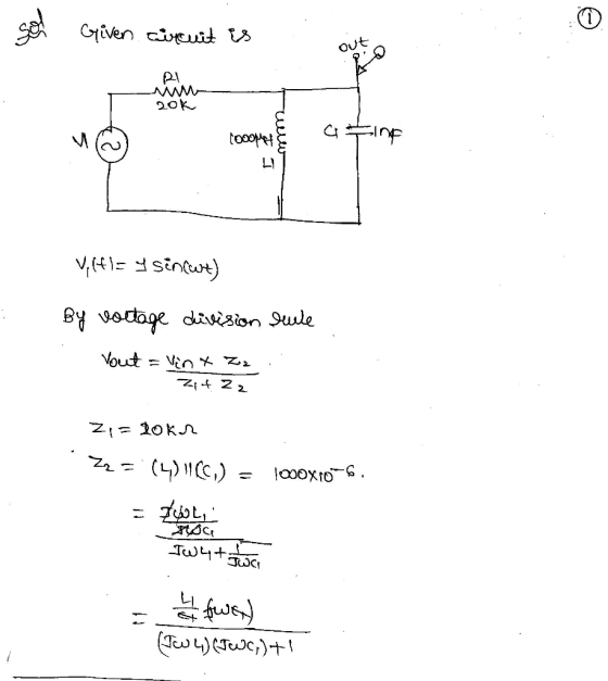
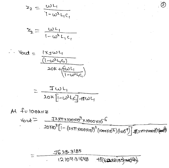
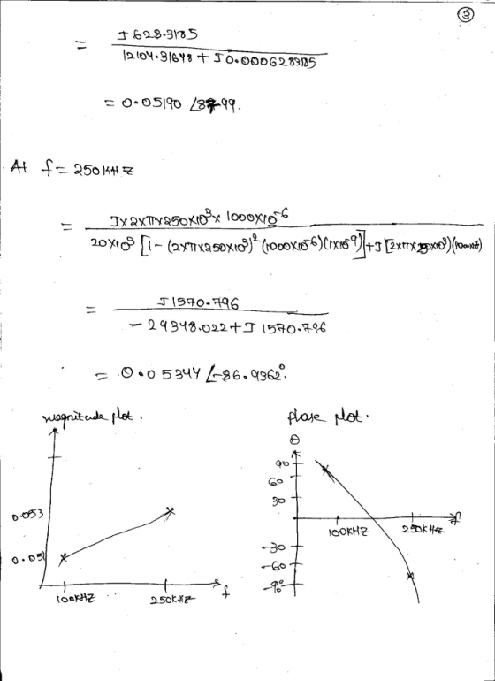
Add Answer to:
Problem 2. Determine and graph the output voltage magnitude, and phase versus frequency for the circuit...
Determine and graph the output voltage magnitude, and phase versus frequency for the circuit shown below....
 Determine and graph the output voltage magnitude, and phase versus frequency for the circuit shown below. The voltage source Vi (t) -1 sin (wt) volts. In your numerical calculations, limit the frequency range from 100 KHz to 250 KHz. out R1 20k 1000uH V1 C11n L1 0
L1 s] CI ?2 s2 In the circuit, the amplitude and phase of the voltage source...
 L1 s] CI ?2 s2 In the circuit, the amplitude and phase of the voltage source Vs1 are 120 V and 0.4 rad, those of the voltage source Vs2 are 230 V and 0.5 rad, the voltage frequency is 20 kHz; 36 mH, L2 20 mH, C1 2.5 nF R1-3 kOhm, R2 7 kOhm, R36 kOhm, L1 Find the impedance of inductor L1 Real part of impedance (Ohm) Submit Answer Tries 0/3 Impaginary part of impedance (Ohm): Submit Answer Tries...
WIth the following two circuits (Circuit A and B), please derive the equations for the magnitude...
 WIth the following two circuits (Circuit A and B), please derive
the equations for the magnitude and phase of the capacitor and
inductor voltage as a function of angular frequency ω, and plot the
values in MATLAB or Excel.
Both circuits have the voltage set to AC Amplitude 1 and an AC
Phase to 0 degrees.
Circuit A:
Circuit B:
Thanks.
R1 100 V1 L1 AC 1 0 10mH
WIth the following two circuits (Circuit A and B), please derive
the equations for the magnitude and phase of the capacitor and
inductor voltage as a function of angular frequency ω, and plot the
values in MATLAB or Excel.
Both circuits have the voltage set to AC Amplitude 1 and an AC
Phase to 0 degrees.
Circuit A:
Circuit B:
Thanks.
R1 100 V1 L1 AC 1 0 10mH
2.2kn 10nF Fig. 1. Resistive-capacitive circuit for learning how to measure magnitude and phase shift. 1....
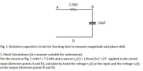 2.2kn 10nF Fig. 1. Resistive-capacitive circuit for learning how to measure magnitude and phase shift. 1. Hand Calculations (in a manner suitable for submission) For the circuit in Fig. 1 with f = 7.2 kHz and a source t) = 1.0 cos (Zrf-t|v applied at the circuit input (between points A and D), calculate by hand the voltage vi(t) at the input and the voltage v2(t) at the output (between points B and D).
Voltage Pulse Response of a RC Circuit PULSE VOLTAGE Label Display Fut Pins Variant Pulau R1...
 Voltage Pulse Response of a RC Circuit PULSE VOLTAGE Label Display Fut Pins Variant Pulau R1 Pue with 1kg V1 OV 10V 2ms 4ms 1F Distortion frecuenche = Cancel Help f) For the circuit and Pulse Voltage parameters shown above, enter the circuit using Multisim Schematic Capture. g) Simulate using Transient mode with a graphical output. a. Explain the resulting graphical waveform by answering the following questions: i. Why is the amplitude look like a "sawtooth" shape? ii. What is...
To describe the phase relation between current and voltage, we use particular words: In the circuit...
 To describe the phase relation between current and voltage, we use particular words: In the circuit represented by these phasors, the current the voltage, leads lags is perpendicular to is out of phase with The appropriate answer here is B although C and D are also correct. Explain what answer B means: A capacitor has a peak current of 330 mu A when the peak voltage at f = 250 kHz is 2.2 V. What is the capacitance C? If...
An AC voltage source has an output of ∆V = 172.0 sin(408t) Volts. 1. Calculate the...
An AC voltage source has an output of ∆V = 172.0 sin(408t) Volts. 1. Calculate the RMS voltage. 2. What is the frequency of the source? 3. Calculate the voltage at time t = 1/104 s. 4. Calculate the maximum current in the circuit when the generator is connected to an R = 56.0 Ω resistor.
2. In the circuit below, R1 = 10k, R2 : magnitude is applied to the input....
 2. In the circuit below, R1 = 10k, R2 : magnitude is applied to the input. Find V(t) at the output and sketch it. Your sketch should be quantitatively correct, that is, it should have labeled V and t axes. Strongly suggested: solve by first finding the Thévenin equivalent of the source voltage and resistor network. 20k and C = 0.1µF. At t = 0, a step function of 10 V Input (problem 3) R, 10V- IN R2 C, OUT...
Plot the gain-versus-frequency curve and phase-versus-frequency curve for the following circuit. 100 kΩ Input 1 kΩ...
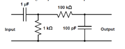 Plot the gain-versus-frequency
curve and phase-versus-frequency curve for the following
circuit.
100 kΩ Input 1 kΩ 100 pF Output
Plot the gain-versus-frequency
curve and phase-versus-frequency curve for the following
circuit.
100 kΩ Input 1 kΩ 100 pF Output
Problem: (1) For the single phase AC circuit shown below, calculate voltage phasor across the loa...
 Problem: (1) For the single phase AC circuit shown below, calculate voltage phasor across the load showing amplitude and phase angle for a (reference) source voltage of 220 V and 0 degree. Also, attach your MultiSIM simulation showing the voltage amplitude across the load. Compare simulated and calculated values. Load Bus of an Industrial Facility (equivalent of Electrical Motors and power factor correction Cap in parallel). R1 L1 Vload-? 1 3.0ohm 2 10mH 3 4.7mH 4 20ohm R2 +220V, 60...
 Determine and graph the output voltage magnitude, and phase versus frequency for the circuit shown below. The voltage source Vi (t) -1 sin (wt) volts. In your numerical calculations, limit the frequency range from 100 KHz to 250 KHz. out R1 20k 1000uH V1 C11n L1 0
 L1 s] CI ?2 s2 In the circuit, the amplitude and phase of the voltage source Vs1 are 120 V and 0.4 rad, those of the voltage source Vs2 are 230 V and 0.5 rad, the voltage frequency is 20 kHz; 36 mH, L2 20 mH, C1 2.5 nF R1-3 kOhm, R2 7 kOhm, R36 kOhm, L1 Find the impedance of inductor L1 Real part of impedance (Ohm) Submit Answer Tries 0/3 Impaginary part of impedance (Ohm): Submit Answer Tries...
 WIth the following two circuits (Circuit A and B), please derive
the equations for the magnitude and phase of the capacitor and
inductor voltage as a function of angular frequency ω, and plot the
values in MATLAB or Excel.
Both circuits have the voltage set to AC Amplitude 1 and an AC
Phase to 0 degrees.
Circuit A:
Circuit B:
Thanks.
R1 100 V1 L1 AC 1 0 10mH
WIth the following two circuits (Circuit A and B), please derive
the equations for the magnitude and phase of the capacitor and
inductor voltage as a function of angular frequency ω, and plot the
values in MATLAB or Excel.
Both circuits have the voltage set to AC Amplitude 1 and an AC
Phase to 0 degrees.
Circuit A:
Circuit B:
Thanks.
R1 100 V1 L1 AC 1 0 10mH
 2.2kn 10nF Fig. 1. Resistive-capacitive circuit for learning how to measure magnitude and phase shift. 1. Hand Calculations (in a manner suitable for submission) For the circuit in Fig. 1 with f = 7.2 kHz and a source t) = 1.0 cos (Zrf-t|v applied at the circuit input (between points A and D), calculate by hand the voltage vi(t) at the input and the voltage v2(t) at the output (between points B and D).
 Voltage Pulse Response of a RC Circuit PULSE VOLTAGE Label Display Fut Pins Variant Pulau R1 Pue with 1kg V1 OV 10V 2ms 4ms 1F Distortion frecuenche = Cancel Help f) For the circuit and Pulse Voltage parameters shown above, enter the circuit using Multisim Schematic Capture. g) Simulate using Transient mode with a graphical output. a. Explain the resulting graphical waveform by answering the following questions: i. Why is the amplitude look like a "sawtooth" shape? ii. What is...
 To describe the phase relation between current and voltage, we use particular words: In the circuit represented by these phasors, the current the voltage, leads lags is perpendicular to is out of phase with The appropriate answer here is B although C and D are also correct. Explain what answer B means: A capacitor has a peak current of 330 mu A when the peak voltage at f = 250 kHz is 2.2 V. What is the capacitance C? If...
 2. In the circuit below, R1 = 10k, R2 : magnitude is applied to the input. Find V(t) at the output and sketch it. Your sketch should be quantitatively correct, that is, it should have labeled V and t axes. Strongly suggested: solve by first finding the Thévenin equivalent of the source voltage and resistor network. 20k and C = 0.1µF. At t = 0, a step function of 10 V Input (problem 3) R, 10V- IN R2 C, OUT...
 Plot the gain-versus-frequency
curve and phase-versus-frequency curve for the following
circuit.
100 kΩ Input 1 kΩ 100 pF Output
Plot the gain-versus-frequency
curve and phase-versus-frequency curve for the following
circuit.
100 kΩ Input 1 kΩ 100 pF Output
 Problem: (1) For the single phase AC circuit shown below, calculate voltage phasor across the load showing amplitude and phase angle for a (reference) source voltage of 220 V and 0 degree. Also, attach your MultiSIM simulation showing the voltage amplitude across the load. Compare simulated and calculated values. Load Bus of an Industrial Facility (equivalent of Electrical Motors and power factor correction Cap in parallel). R1 L1 Vload-? 1 3.0ohm 2 10mH 3 4.7mH 4 20ohm R2 +220V, 60...
Most questions answered within 3 hours.
-
Where is the error in this code sequence?
String s1 = "Hello";
String s2 = "ello";...
asked 11 months ago -
Financial data for Joel de Paris, Inc., for last year
follow:
Joel de Paris, Inc.
Balance...
asked 11 months ago -
Consider this reaction:
Al2(SO4)3 (aq)+ BaCl3
(aq) Al2Cl6 (aq)- +
3BaSO4(s) . What is the...
asked 11 months ago -
Suppose that Savneet is considering increasing her
recent random sample from 20 car rentals to 40...
asked 11 months ago -
Trucks arrive at an unloading terminal at an average rate of 120
per hour.
Trucks arrive...
asked 11 months ago -
Why are methanol and ethanol completely soluble in water while
octanol is not very little soluble....
asked 11 months ago -
A facilities manager at a university reads in a research report
that the mean amount of...
asked 11 months ago -
When the CuSO4 is rehydrated by adding water to the anhydrous
compound, is this an endothermic...
asked 11 months ago -
A ray of sunlight is passing from diamond into crown glass; the
angle of incidence is...
asked 11 months ago -
A block of mass 0.249 kg is placed on top of a light, vertical
spring of...
asked 11 months ago -
how do the kidneys compensate in the presences of acidosis
a) trigger hyperventilate
b) reserve acid...
asked 11 months ago -
Question 501 pts
The rental rate of capital to the firm increases. Which of the
following...
asked 11 months ago