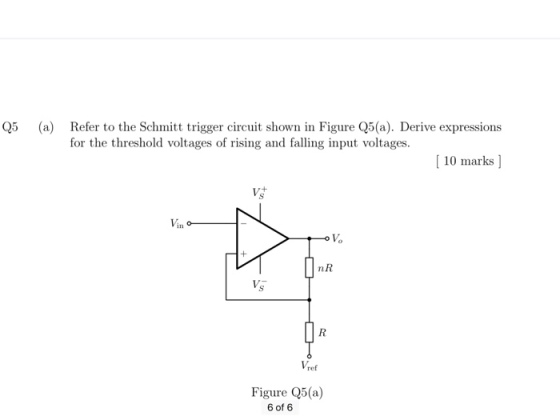
Q5a Refer to Schmitt trigger shown. Derive expression for threshold voltages of rising and falling input...
Homework Answers

Add Answer to:
Q5a
Refer to Schmitt trigger shown. Derive expression for threshold
voltages of rising and falling input...
(a.) Design a noninverting Schmitt trigger circuit with transition voltages of -2.5 V and +5 V....
(a.) Design a noninverting Schmitt trigger circuit with transition voltages of -2.5 V and +5 V. Assume ± Vsat = ± 15 V and that vin = 8sin(100pt) V. Show all design work. Sketch the circuit schematic (showing the required resistor ratios and the specific value of any required external voltages)..
(a) Design a inverting Schmitt trigger circuit to be used as a zero crossing detector with transition voltages about ±25...
 (a) Design a inverting Schmitt trigger circuit
to be used as a zero crossing detector with transition voltages
about ±25 mV. Assume the saturation voltages for the op–amp are ±13
V. Draw the voltage transfer characteristic (VTC), i.e., vout vs.
vin.
(b) Design an astable multivibrator to produce
a square signal with a frequency of 1 kHz using C=0.01 µF, R1 = 30
kΩ, and R2 = 20 kΩ. Sketch the circuit waveforms (vo, v +, and v −)
assuming...
(a) Design a inverting Schmitt trigger circuit
to be used as a zero crossing detector with transition voltages
about ±25 mV. Assume the saturation voltages for the op–amp are ±13
V. Draw the voltage transfer characteristic (VTC), i.e., vout vs.
vin.
(b) Design an astable multivibrator to produce
a square signal with a frequency of 1 kHz using C=0.01 µF, R1 = 30
kΩ, and R2 = 20 kΩ. Sketch the circuit waveforms (vo, v +, and v −)
assuming...
1. Draw and completely label the Vout versus Vin for the Schmitt trigger device whose Vin...
 1. Draw and completely label the Vout versus Vin for the Schmitt trigger device whose Vin waveforms are given? 7414 28- М. 2. One particular Schmitt trigger inverter has a positive-going threshold of 1.9 V and a negative going threshold of 0.7 V. Its Voh is 3.6 V and VoL is 0.2 V. Sketch the Vo when Vin waveforms is shown below 2.0 V 1,6 V Vin 1.2 v <<< < 14-3. The capacitor initially discharged. Howe long after the...
3) For the Bistable circuit shown, a) Derive expressions for the threshold voltages VTL and Vth...
 3) For the Bistable circuit shown, a) Derive expressions for the threshold voltages VTL and Vth in terms of the op- amp's saturation level L+, L_, R1, R2, R3, and V. b) Let L+ = -L_ = 7.5 V, V = 12.5 V, and R1 = 2 k.2. Find the values of R2 and R3 that result in VTL = +4.75 V and Vth = +5.25 V. OV R3 R2 w R w vo
Review questions. 22 Comparators and the Schmitt Trigger Reading: Floyd and Buchla, Analog Fundamentals: A Systems...
 Review questions.
22 Comparators and the Schmitt Trigger Reading: Floyd and Buchla, Analog Fundamentals: A Systems Approach, Section 8-1 Objectives: After performing this experiment, you will be able to: 1. 2. Compare the input and output waveforms for comparator and Schmitt trigger circuits. Use an oscilloscope to plot the transfer curve for a comparator circuit, including one with hysteresis truct and test a relaxation oscillator using a Schmitt trigger. Summary of Theory: A comparator is a switching device that produces...
Review questions.
22 Comparators and the Schmitt Trigger Reading: Floyd and Buchla, Analog Fundamentals: A Systems Approach, Section 8-1 Objectives: After performing this experiment, you will be able to: 1. 2. Compare the input and output waveforms for comparator and Schmitt trigger circuits. Use an oscilloscope to plot the transfer curve for a comparator circuit, including one with hysteresis truct and test a relaxation oscillator using a Schmitt trigger. Summary of Theory: A comparator is a switching device that produces...
+Vcc w CT U1 U2 T. u1 Trigger Input T RT Ov Simultaneously draw the voltages...
 +Vcc w CT U1 U2 T. u1 Trigger Input T RT Ov Simultaneously draw the voltages V1 and VQ on the side CMOS oscillator circuit and find the expression of the output frequency. NOTE: Omit output impedances (Rout = 0)..
9) Assume that the transistors shown below have the following threshold voltages: VTN = 1V and...
 9) Assume that the transistors shown below have the following threshold voltages: VTN = 1V and VTP = -1V. Further assume that there are parasitic capacitors at the nodes: Vo1 through Vo6 and that these capacitors are initially discharged when the voltages shown on the circuit are applied. Determine Vo1, Vo2, Vo3, Vo4, Vos and Vo6. 15V 5v 5V Vo1 Vo2 5V Vo3 15V 10V 5V Vo4 Vo5 Vo6 lov 15V
Question 3 5 out of 5 points Analyze the circuit below to derive an expression for...
 Question 3 5 out of 5 points Analyze the circuit below to derive an expression for lout in terms of the input voltages, Va and Vb. Assume R1-R2-R3-R4-R. Assume the op-amp is operating in its linear region. Va R1 R2 OA2 LM741 Vb R3 R4 lout RL
1. Derive the gain expression for the following instrument amplifier shown in Figure 1. 2. Derive...
 1. Derive the gain expression for the following instrument amplifier shown in Figure 1. 2. Derive the Transfer function for the circuit shown in Figure 2. 10K R7R6 R2B R38 RiR4 10K 10K R5 Figure 1 Figure 2
11. Derive an expression for the center of the mass for the boomerang shown below. The...
 11. Derive an expression for the center of the mass for the boomerang shown below. The boomerang is composed of 2 uniform rods.
 (a) Design a inverting Schmitt trigger circuit
to be used as a zero crossing detector with transition voltages
about ±25 mV. Assume the saturation voltages for the op–amp are ±13
V. Draw the voltage transfer characteristic (VTC), i.e., vout vs.
vin.
(b) Design an astable multivibrator to produce
a square signal with a frequency of 1 kHz using C=0.01 µF, R1 = 30
kΩ, and R2 = 20 kΩ. Sketch the circuit waveforms (vo, v +, and v −)
assuming...
(a) Design a inverting Schmitt trigger circuit
to be used as a zero crossing detector with transition voltages
about ±25 mV. Assume the saturation voltages for the op–amp are ±13
V. Draw the voltage transfer characteristic (VTC), i.e., vout vs.
vin.
(b) Design an astable multivibrator to produce
a square signal with a frequency of 1 kHz using C=0.01 µF, R1 = 30
kΩ, and R2 = 20 kΩ. Sketch the circuit waveforms (vo, v +, and v −)
assuming...
 1. Draw and completely label the Vout versus Vin for the Schmitt trigger device whose Vin waveforms are given? 7414 28- М. 2. One particular Schmitt trigger inverter has a positive-going threshold of 1.9 V and a negative going threshold of 0.7 V. Its Voh is 3.6 V and VoL is 0.2 V. Sketch the Vo when Vin waveforms is shown below 2.0 V 1,6 V Vin 1.2 v <<< < 14-3. The capacitor initially discharged. Howe long after the...
 3) For the Bistable circuit shown, a) Derive expressions for the threshold voltages VTL and Vth in terms of the op- amp's saturation level L+, L_, R1, R2, R3, and V. b) Let L+ = -L_ = 7.5 V, V = 12.5 V, and R1 = 2 k.2. Find the values of R2 and R3 that result in VTL = +4.75 V and Vth = +5.25 V. OV R3 R2 w R w vo
 Review questions.
22 Comparators and the Schmitt Trigger Reading: Floyd and Buchla, Analog Fundamentals: A Systems Approach, Section 8-1 Objectives: After performing this experiment, you will be able to: 1. 2. Compare the input and output waveforms for comparator and Schmitt trigger circuits. Use an oscilloscope to plot the transfer curve for a comparator circuit, including one with hysteresis truct and test a relaxation oscillator using a Schmitt trigger. Summary of Theory: A comparator is a switching device that produces...
Review questions.
22 Comparators and the Schmitt Trigger Reading: Floyd and Buchla, Analog Fundamentals: A Systems Approach, Section 8-1 Objectives: After performing this experiment, you will be able to: 1. 2. Compare the input and output waveforms for comparator and Schmitt trigger circuits. Use an oscilloscope to plot the transfer curve for a comparator circuit, including one with hysteresis truct and test a relaxation oscillator using a Schmitt trigger. Summary of Theory: A comparator is a switching device that produces...
 +Vcc w CT U1 U2 T. u1 Trigger Input T RT Ov Simultaneously draw the voltages V1 and VQ on the side CMOS oscillator circuit and find the expression of the output frequency. NOTE: Omit output impedances (Rout = 0)..
 9) Assume that the transistors shown below have the following threshold voltages: VTN = 1V and VTP = -1V. Further assume that there are parasitic capacitors at the nodes: Vo1 through Vo6 and that these capacitors are initially discharged when the voltages shown on the circuit are applied. Determine Vo1, Vo2, Vo3, Vo4, Vos and Vo6. 15V 5v 5V Vo1 Vo2 5V Vo3 15V 10V 5V Vo4 Vo5 Vo6 lov 15V
 Question 3 5 out of 5 points Analyze the circuit below to derive an expression for lout in terms of the input voltages, Va and Vb. Assume R1-R2-R3-R4-R. Assume the op-amp is operating in its linear region. Va R1 R2 OA2 LM741 Vb R3 R4 lout RL
 1. Derive the gain expression for the following instrument amplifier shown in Figure 1. 2. Derive the Transfer function for the circuit shown in Figure 2. 10K R7R6 R2B R38 RiR4 10K 10K R5 Figure 1 Figure 2
 11. Derive an expression for the center of the mass for the boomerang shown below. The boomerang is composed of 2 uniform rods.
Most questions answered within 3 hours.
-
Where is the error in this code sequence?
String s1 = "Hello";
String s2 = "ello";...
asked 10 months ago -
Financial data for Joel de Paris, Inc., for last year
follow:
Joel de Paris, Inc.
Balance...
asked 10 months ago -
Consider this reaction:
Al2(SO4)3 (aq)+ BaCl3
(aq) Al2Cl6 (aq)- +
3BaSO4(s) . What is the...
asked 10 months ago -
Suppose that Savneet is considering increasing her
recent random sample from 20 car rentals to 40...
asked 10 months ago -
Trucks arrive at an unloading terminal at an average rate of 120
per hour.
Trucks arrive...
asked 10 months ago -
Why are methanol and ethanol completely soluble in water while
octanol is not very little soluble....
asked 10 months ago -
A facilities manager at a university reads in a research report
that the mean amount of...
asked 10 months ago -
When the CuSO4 is rehydrated by adding water to the anhydrous
compound, is this an endothermic...
asked 10 months ago -
A ray of sunlight is passing from diamond into crown glass; the
angle of incidence is...
asked 10 months ago -
A block of mass 0.249 kg is placed on top of a light, vertical
spring of...
asked 10 months ago -
how do the kidneys compensate in the presences of acidosis
a) trigger hyperventilate
b) reserve acid...
asked 10 months ago -
Question 501 pts
The rental rate of capital to the firm increases. Which of the
following...
asked 10 months ago