
Homework Answers
From Figure
| Element | Anlge | cos(theta) | sin(theta) | cos(theta)^2 | sin(theta)^2 | sin(theta)*cos(theta) |
| 1 | 90 | 0 | 1 | 0 | 1 | 0 |
| 2 | 0 | 1 | 0 | 1 | 0 | 0 |
| 3 | 0 | 1 | 0 | 1 | 0 | 0 |
| 4 | -90 | 0 | -1 | 0 | 1 | 0 |
and as per given data
| E | 2.1*1011 | Pa |
| L | 6 | m |
| A | 0.01 | m2 |
| I | 0.0001 | m4 |
| 12*I/L2 | 3.33333*10-05 | m2 |
| 6*I/L | 0.0001 | m3 |
| E/L | 35000000000 | Pa/m |
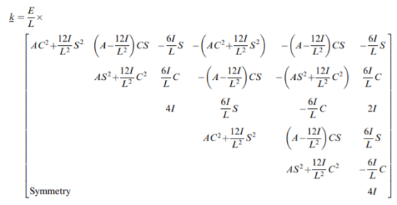
So from data the K matrix are,


as per figure node 1 and node 4 are fixed joint and node 2 and node 3 are pin joint so

As per given force and moment


Global K matrix

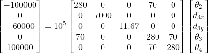
For finding the deflection and rotation we have to terminate row and column except 6,7,8,9,12
![1280 o o 70 о] о 7000 o o o К = 10° | о о 11.67 o o | 70 o o 280 70 | o o o 70 280 | [ 382.65 o o o 14.29 o К-1-10-10 | o o 8](http://img.homeworklib.com/questions/5e2b22f0-c960-11eb-9fd8-dd9a7516ead3.png?x-oss-process=image/resize,w_560)
AS we know

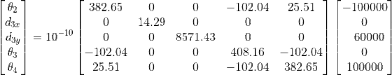

so,
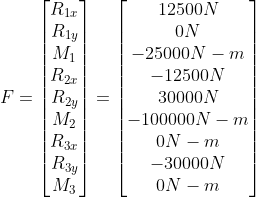
Reaction force at other node are given by,


other method to find the solution is
the strucher is symetric so just perfom it for half strucher so,
| Element | Anlge | cos(theta) | sin(theta) | cos(theta)^2 | sin(theta)^2 | sin(theta)*cos(theta) |
| 1 | 90 | 0 | 1 | 0 | 1 | 0 |
| 2 | 0 | 1 | 0 | 1 | 0 | 0 |
| 3 | 0 | 1 | 0 | 1 | 0 | 0 |
| 4 | -90 | 0 | -1 | 0 | 1 | 0 |
and as per given data
| E | 2.1*1011 | Pa |
| L | 6 | m |
| A | 0.01 | m2 |
| I | 0.0001 | m4 |
| 12*I/L2 | 3.33333*10-05 | m2 |
| 6*I/L | 0.0001 | m3 |
| E/L | 35000000000 | Pa/m |
So from data the K matrix are,


as per figure node 1 and node 4 are fixed joint and node 2 and node 3 are pin joint so

As per given force and moment


For finding the deflection and rotation we have to terminate row and column and row 1,2,3,4,5,from K,F,D matrix

![D] = [K-F](http://img.homeworklib.com/questions/66948a90-c960-11eb-a230-896a238505da.png?x-oss-process=image/resize,w_560)

Reaction forces:
Same will be act on other halft portion

Total F matrix

Add Answer to:
by finite elemnt method
4. (25 points) Using symmetry on the frame shown below, solve for...
Week 9, Question 2: Use the stiffness method to analyse the elastic frame ABC shown below....
 Week 9, Question 2: Use the stiffness method to analyse the elastic frame ABC shown below. Use a model made up of 2 the elements (AB and CB) and the axis indicated in the figure. All members have the following properties: E = 2 ·10kPa, A = 0.005 m², 1 = 1.5e – 4 m+.. Also the lengths of the elements are the same: AB = BC = L = 6.5 m and w = 12 kN/m. 0 А x...
Use the stiffness method to analyse the elastic frame ABC shown below. Use a model made...
 Use the stiffness method to analyse the elastic frame ABC shown below. Use a model made up of 2 the elements (AB and CB) and the axis indicated in the figure. All members have the following properties: E = 2 -10% kPa, A = 0.005 m², 1 = 1.5e - 4 m. Also the lengths of the elements are the same: AB = BC = L = 3.1 m and 6 = 45 kN/m. ות 0 B 3 2 x...
Solve all problems using the finite element stiffness method. For the rigid frame shown in Figure...
 Solve all problems using the finite element stiffness method. For the rigid frame shown in Figure P5-4, determine (1) the nodal displacements and rotation at node 4, (2) the reactions, and (3) the forces in each element. Then check equilibrium at node 4. Finally, draw the shear force and bending moment diagrams for each element. LetE 30 x 103 ksi, A = 8 in,2 , and 1-800 in.4 for all elements. 20 kip 25 ft 25 ft- 40 ft 20...
Using the Stiffness Method procedure identify nodes, elements and degrees of freedom (neglect axial stiffness) for the beam shown below. Form member and structure stiffness matrices and compute displ...
 Using the Stiffness Method procedure identify nodes, elements and degrees of freedom (neglect axial stiffness) for the beam shown below. Form member and structure stiffness matrices and compute displacements, reactions and internal forces developed in the beam Note that there is a hinge at B. Take E = 250 GPa, 1-2000 cm 10 kN 2 kN/m 5 kN-m 10 m
Using the Stiffness Method procedure identify nodes, elements and degrees of freedom (neglect axial stiffness) for the beam shown below....
Using the Stiffness Method procedure identify nodes, elements and degrees of freedom (neglect axial stiffness) for the beam shown below. Form member and structure stiffness matrices and compute displacements, reactions and internal forces developed in the beam Note that there is a hinge at B. Take E = 250 GPa, 1-2000 cm 10 kN 2 kN/m 5 kN-m 10 m
Using the Stiffness Method procedure identify nodes, elements and degrees of freedom (neglect axial stiffness) for the beam shown below....
Using the Stiffness Method procedure identify nodes, elements and degrees of freedom (neglect axial stiffness) for the beam shown below. Form member and structure stiffness matrices and compute di...
 Using the Stiffness Method procedure identify nodes, elements and degrees of freedom (neglect axial stiffness) for the beam shown below. Form member and structure stiffness matrices and compute displacements, reactions and internal forces developed in the beam. Note that there is a hinge at B. Take E= 250 G Pa, 1 = 2000 cm- 10 kN 5 kN-m 2 kN/m 10 m
Using the Stiffness Method procedure identify nodes, elements and degrees of freedom (neglect axial stiffness) for the beam...
Using the Stiffness Method procedure identify nodes, elements and degrees of freedom (neglect axial stiffness) for the beam shown below. Form member and structure stiffness matrices and compute displacements, reactions and internal forces developed in the beam. Note that there is a hinge at B. Take E= 250 G Pa, 1 = 2000 cm- 10 kN 5 kN-m 2 kN/m 10 m
Using the Stiffness Method procedure identify nodes, elements and degrees of freedom (neglect axial stiffness) for the beam...
For the system shown below, (a) the global stiffness matrix (b)displacements of nodes 2 and 3...
 For the system shown below, (a) the global stiffness
matrix (b)displacements of nodes 2 and 3 (c)the
reaction forces at nodes 1 and 4 (d)the force in the
members
EA TRATAMI 70-400 = 100 x 10 kN/m 0.28 ATT L ( EA k, 100 - 200 = 200 x 10 kN/m 0.1 L (4 EA k, 200.70 =140x10 kN/m 0.1 I (4.2 X tretiet 0.28 2 vyos Imool
For the system shown below, (a) the global stiffness
matrix (b)displacements of nodes 2 and 3 (c)the
reaction forces at nodes 1 and 4 (d)the force in the
members
EA TRATAMI 70-400 = 100 x 10 kN/m 0.28 ATT L ( EA k, 100 - 200 = 200 x 10 kN/m 0.1 L (4 EA k, 200.70 =140x10 kN/m 0.1 I (4.2 X tretiet 0.28 2 vyos Imool
Solve all problems using the finite element stiffness method. For the rigid frame shown in Figure P5-4, determine (1) the nodal displacements and rotation at node 4, (2) the reactions, and (3) the fo...
 Solve all problems using the finite element stiffness method. For the rigid frame shown in Figure P5-4, determine (1) the nodal displacements and rotation at node 4, (2) the reactions, and (3) the forces in each element. Then check equilibrium at node 4 Finally, draw the shear force and bending moment diagrams for each element. Let E 30x 103 ksi, A 8 in2, and I 800 in.4 for all elements. 20 kip 25 ft 25 ft 40 ft Figure P5-4...
Use the stiffness method to analyse the elastic frame ABC shown below. Use a model made...
 Use the stiffness method to analyse the elastic frame ABC shown below. Use a model made up of 2 the elements (AB and CB) and the axis indicated in the figure. All members have the following properties: E=2.108 kPa, A = 0.005 m², 1 = 1.5e - 4 m4. Also the lengths of the elements are the same: AB = BC = L = 4.7 m and w=17 kN/m. - B Structure, loading, member axes Degrees of freedom Calculate the...
 Week 9, Question 2: Use the stiffness method to analyse the elastic frame ABC shown below. Use a model made up of 2 the elements (AB and CB) and the axis indicated in the figure. All members have the following properties: E = 2 ·10kPa, A = 0.005 m², 1 = 1.5e – 4 m+.. Also the lengths of the elements are the same: AB = BC = L = 6.5 m and w = 12 kN/m. 0 А x...
 Use the stiffness method to analyse the elastic frame ABC shown below. Use a model made up of 2 the elements (AB and CB) and the axis indicated in the figure. All members have the following properties: E = 2 -10% kPa, A = 0.005 m², 1 = 1.5e - 4 m. Also the lengths of the elements are the same: AB = BC = L = 3.1 m and 6 = 45 kN/m. ות 0 B 3 2 x...
 Use the stiffness method to analyse the elastic frame ABC shown below. Use a model made up of 2 the elements (AB and CB) and the axis indicated in the figure. All members have the following properties: E = 2 -10% kPa, A = 0.005 m², 1 = 1.5e - 4 m. Also the lengths of the elements are the same: AB = BC = L = 3.1 m and 6 = 45 kN/m. ות 0 B 3 2 x...
 Use the stiffness method to analyse the elastic frame ABC shown below. Use a model made up of 2 the elements (AB and CB) and the axis indicated in the figure. All members have the following properties: E = 2 -10% kPa, A = 0.005 m², 1 = 1.5e - 4 m. Also the lengths of the elements are the same: AB = BC = L = 3.1 m and 6 = 45 kN/m. ות 0 B 3 2 x...
 Solve all problems using the finite element stiffness method. For the rigid frame shown in Figure P5-4, determine (1) the nodal displacements and rotation at node 4, (2) the reactions, and (3) the forces in each element. Then check equilibrium at node 4. Finally, draw the shear force and bending moment diagrams for each element. LetE 30 x 103 ksi, A = 8 in,2 , and 1-800 in.4 for all elements. 20 kip 25 ft 25 ft- 40 ft 20...
 Using the Stiffness Method procedure identify nodes, elements and degrees of freedom (neglect axial stiffness) for the beam shown below. Form member and structure stiffness matrices and compute displacements, reactions and internal forces developed in the beam Note that there is a hinge at B. Take E = 250 GPa, 1-2000 cm 10 kN 2 kN/m 5 kN-m 10 m
Using the Stiffness Method procedure identify nodes, elements and degrees of freedom (neglect axial stiffness) for the beam shown below....
Using the Stiffness Method procedure identify nodes, elements and degrees of freedom (neglect axial stiffness) for the beam shown below. Form member and structure stiffness matrices and compute displacements, reactions and internal forces developed in the beam Note that there is a hinge at B. Take E = 250 GPa, 1-2000 cm 10 kN 2 kN/m 5 kN-m 10 m
Using the Stiffness Method procedure identify nodes, elements and degrees of freedom (neglect axial stiffness) for the beam shown below....
 Using the Stiffness Method procedure identify nodes, elements and degrees of freedom (neglect axial stiffness) for the beam shown below. Form member and structure stiffness matrices and compute displacements, reactions and internal forces developed in the beam. Note that there is a hinge at B. Take E= 250 G Pa, 1 = 2000 cm- 10 kN 5 kN-m 2 kN/m 10 m
Using the Stiffness Method procedure identify nodes, elements and degrees of freedom (neglect axial stiffness) for the beam...
Using the Stiffness Method procedure identify nodes, elements and degrees of freedom (neglect axial stiffness) for the beam shown below. Form member and structure stiffness matrices and compute displacements, reactions and internal forces developed in the beam. Note that there is a hinge at B. Take E= 250 G Pa, 1 = 2000 cm- 10 kN 5 kN-m 2 kN/m 10 m
Using the Stiffness Method procedure identify nodes, elements and degrees of freedom (neglect axial stiffness) for the beam...
 For the system shown below, (a) the global stiffness
matrix (b)displacements of nodes 2 and 3 (c)the
reaction forces at nodes 1 and 4 (d)the force in the
members
EA TRATAMI 70-400 = 100 x 10 kN/m 0.28 ATT L ( EA k, 100 - 200 = 200 x 10 kN/m 0.1 L (4 EA k, 200.70 =140x10 kN/m 0.1 I (4.2 X tretiet 0.28 2 vyos Imool
For the system shown below, (a) the global stiffness
matrix (b)displacements of nodes 2 and 3 (c)the
reaction forces at nodes 1 and 4 (d)the force in the
members
EA TRATAMI 70-400 = 100 x 10 kN/m 0.28 ATT L ( EA k, 100 - 200 = 200 x 10 kN/m 0.1 L (4 EA k, 200.70 =140x10 kN/m 0.1 I (4.2 X tretiet 0.28 2 vyos Imool
 Solve all problems using the finite element stiffness method. For the rigid frame shown in Figure P5-4, determine (1) the nodal displacements and rotation at node 4, (2) the reactions, and (3) the forces in each element. Then check equilibrium at node 4 Finally, draw the shear force and bending moment diagrams for each element. Let E 30x 103 ksi, A 8 in2, and I 800 in.4 for all elements. 20 kip 25 ft 25 ft 40 ft Figure P5-4...
 Use the stiffness method to analyse the elastic frame ABC shown below. Use a model made up of 2 the elements (AB and CB) and the axis indicated in the figure. All members have the following properties: E=2.108 kPa, A = 0.005 m², 1 = 1.5e - 4 m4. Also the lengths of the elements are the same: AB = BC = L = 4.7 m and w=17 kN/m. - B Structure, loading, member axes Degrees of freedom Calculate the...
Most questions answered within 3 hours.
-
Where is the error in this code sequence?
String s1 = "Hello";
String s2 = "ello";...
asked 10 months ago -
Financial data for Joel de Paris, Inc., for last year
follow:
Joel de Paris, Inc.
Balance...
asked 10 months ago -
Consider this reaction:
Al2(SO4)3 (aq)+ BaCl3
(aq) Al2Cl6 (aq)- +
3BaSO4(s) . What is the...
asked 10 months ago -
Suppose that Savneet is considering increasing her
recent random sample from 20 car rentals to 40...
asked 10 months ago -
Trucks arrive at an unloading terminal at an average rate of 120
per hour.
Trucks arrive...
asked 10 months ago -
Why are methanol and ethanol completely soluble in water while
octanol is not very little soluble....
asked 10 months ago -
A facilities manager at a university reads in a research report
that the mean amount of...
asked 10 months ago -
When the CuSO4 is rehydrated by adding water to the anhydrous
compound, is this an endothermic...
asked 10 months ago -
A ray of sunlight is passing from diamond into crown glass; the
angle of incidence is...
asked 10 months ago -
A block of mass 0.249 kg is placed on top of a light, vertical
spring of...
asked 10 months ago -
how do the kidneys compensate in the presences of acidosis
a) trigger hyperventilate
b) reserve acid...
asked 10 months ago -
Question 501 pts
The rental rate of capital to the firm increases. Which of the
following...
asked 10 months ago