
Homework Answers
 8
8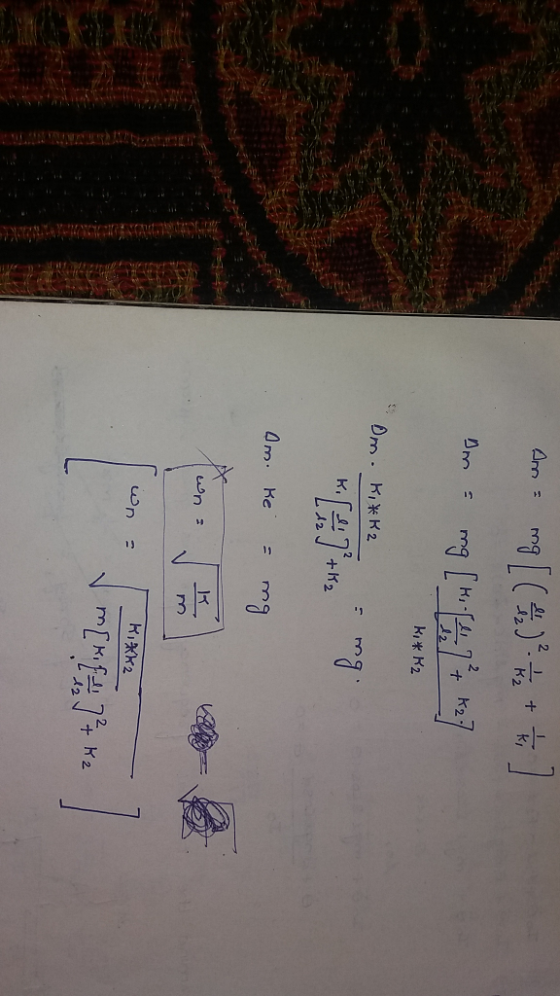
Add Answer to:
2. Consider the system shown in the figure below, comprised of the same motor, steel beam,...
A hinged rigid bar is connected by two springs of stiffnesses kı and k2 and is subjected to a for...
 A hinged rigid bar is connected by two springs of stiffnesses kı and k2 and is subjected to a force F applied at 'D' as shown in the figure. Assuming that the angular displacement of the bar is small (sin θ-6), find the equivalent spring constant of the system that relates the applied force F to the resulting displacement x. 1. ki
A hinged rigid bar is connected by two springs of stiffnesses kı and k2 and is subjected to...
A hinged rigid bar is connected by two springs of stiffnesses kı and k2 and is subjected to a force F applied at 'D' as shown in the figure. Assuming that the angular displacement of the bar is small (sin θ-6), find the equivalent spring constant of the system that relates the applied force F to the resulting displacement x. 1. ki
A hinged rigid bar is connected by two springs of stiffnesses kı and k2 and is subjected to...
10. A hinged rigid bar of length/ is connected by two springs of stiffnesses k1 an and is subjected to a force F as...
 10. A hinged rigid bar of length/ is connected by two springs of stiffnesses k1 an and is subjected to a force F as shown in the figure. Assuming that thean of the displacement of the bar is small (sin θ find the equival system that relates the applied force F at Point D, t d k2 lent spring constant of th o the resulting displacement x.
10. A hinged rigid bar of length/ is connected by two springs of...
10. A hinged rigid bar of length/ is connected by two springs of stiffnesses k1 an and is subjected to a force F as shown in the figure. Assuming that thean of the displacement of the bar is small (sin θ find the equival system that relates the applied force F at Point D, t d k2 lent spring constant of th o the resulting displacement x.
10. A hinged rigid bar of length/ is connected by two springs of...
Problem 2: Cantilever beam In class we derived the spring constant of a beam of length...
 Problem 2: Cantilever beam In class we derived the spring constant of a beam of length L and constant bending stiffness El clamped at x=0 and subject to a vertical force Fat x= L. Let's study a few different variations of that problem. Let's replace the vertical force F by a counter clockwise bending moement Mo applied at x = L. Recom- pute the equivalent spring constant. Note that in the class we computed spring constant with force and displacement....
Consider the mass-spring-damper system depicted in the figure below, where the input of the system is...
 Consider the mass-spring-damper system depicted in the figure below, where the input of the system is the applied force F(t) and the output of the system is xít) that is the displacement of the mass according to the coordinate system defined in that figure. Assume that force F(t) is applied for t> 0 and the system is in static equilibrium before t=0 and z(t) is measured from the static equilibrium. b m F Also, the mass of the block, the...
OUESTİON 2: (30 points) tp() Write the equation of motion for the SDOF system by taking the displ...
 OUESTİON 2: (30 points) tp() Write the equation of motion for the SDOF system by taking the displacement coordinate to be the vertical displacement Z(t) at B. The system is rigid bar having uniformly distributed mass m 4 m 丯k Two concentrated masses m 2ma are located at B and C. The spring and damper are weightless. Assume that all displacements are small. Determine the natural period of the system.
OUESTİON 2: (30 points) tp() Write the equation of motion...
OUESTİON 2: (30 points) tp() Write the equation of motion for the SDOF system by taking the displacement coordinate to be the vertical displacement Z(t) at B. The system is rigid bar having uniformly distributed mass m 4 m 丯k Two concentrated masses m 2ma are located at B and C. The spring and damper are weightless. Assume that all displacements are small. Determine the natural period of the system.
OUESTİON 2: (30 points) tp() Write the equation of motion...
As shown in the figure below, a uniform beam is supported by a cable at one...
 As shown in the figure below, a uniform beam is supported by a
cable at one end and the force of friction at the other end. The
cable makes an angle of θ = 30°,the length of the beam is L= 4.00
m, the coefficient of static friction between the wall and the beam
is μs = 0.500, and the weight of the beam is represented
by w. Determine the minimum distance x from point
A at which an additional...
As shown in the figure below, a uniform beam is supported by a
cable at one end and the force of friction at the other end. The
cable makes an angle of θ = 30°,the length of the beam is L= 4.00
m, the coefficient of static friction between the wall and the beam
is μs = 0.500, and the weight of the beam is represented
by w. Determine the minimum distance x from point
A at which an additional...
As shown in the figure below, a uniform beam is supported by a cable at one...
As shown in the figure below, a uniform beam is supported by a cable at one end and the force of friction at the other end. The cable makes an angle of θ = 30°, the length of the beam is L = 4.25 m, the coefficient of static friction between the wall and the beam is μs = 0.420, and the weight of the beam is represented by w. Determine the minimum distance x from point A at which...
Consider the inverted pendulum system shown below. The inverted pendulum is mounted on top of a...
 Consider the inverted pendulum system shown below. The inverted pendulum is mounted on top of a motor driven cart. The pendulum and cart have two degrees of freedom in plane together, i.e x and θ. It is desired to keep the pendulum upright in the presence of disturbances, such as unexpected force applied on the cart. The slanted pendulum can be brought back to the vertical position by applying a control force u applied to the cart. Once the pendulum...
Question8 n the spring-mass-damper system in Figure 8, the force F, is applied to the mass and it...
 Question8 n the spring-mass-damper system in Figure 8, the force F, is applied to the mass and its displacement is measured via r(t), whilst k and c are the spring and damper constants, respectively x(t) Figure 8: A spring-mass-damper system. a) Obtain the differential equation that relates the input force F, to the measured dis- (6 marks) placement x(t) for the system in Figure 8. b) Draw the block diagram representation of the system in Figure 8. c) Based on...
3) For the system shown in the figure, the input is the torque T(t) and the...
 3) For the system shown in the figure, the input is the torque T(t) and the outputs are the linear displacements x(t) and the angular displacement θ(t). The equilibrium position corresponds to x 0 0. Note that there is viscous friction between the rack and the surface it slides on. Also, you may treat the small diameter shaft as massless and rigid. mr Clearly state all assumptions to be used for modeling this system. Draw the freebody diagrams. State your...
 A hinged rigid bar is connected by two springs of stiffnesses kı and k2 and is subjected to a force F applied at 'D' as shown in the figure. Assuming that the angular displacement of the bar is small (sin θ-6), find the equivalent spring constant of the system that relates the applied force F to the resulting displacement x. 1. ki
A hinged rigid bar is connected by two springs of stiffnesses kı and k2 and is subjected to...
A hinged rigid bar is connected by two springs of stiffnesses kı and k2 and is subjected to a force F applied at 'D' as shown in the figure. Assuming that the angular displacement of the bar is small (sin θ-6), find the equivalent spring constant of the system that relates the applied force F to the resulting displacement x. 1. ki
A hinged rigid bar is connected by two springs of stiffnesses kı and k2 and is subjected to...
 10. A hinged rigid bar of length/ is connected by two springs of stiffnesses k1 an and is subjected to a force F as shown in the figure. Assuming that thean of the displacement of the bar is small (sin θ find the equival system that relates the applied force F at Point D, t d k2 lent spring constant of th o the resulting displacement x.
10. A hinged rigid bar of length/ is connected by two springs of...
10. A hinged rigid bar of length/ is connected by two springs of stiffnesses k1 an and is subjected to a force F as shown in the figure. Assuming that thean of the displacement of the bar is small (sin θ find the equival system that relates the applied force F at Point D, t d k2 lent spring constant of th o the resulting displacement x.
10. A hinged rigid bar of length/ is connected by two springs of...
 Problem 2: Cantilever beam In class we derived the spring constant of a beam of length L and constant bending stiffness El clamped at x=0 and subject to a vertical force Fat x= L. Let's study a few different variations of that problem. Let's replace the vertical force F by a counter clockwise bending moement Mo applied at x = L. Recom- pute the equivalent spring constant. Note that in the class we computed spring constant with force and displacement....
 Consider the mass-spring-damper system depicted in the figure below, where the input of the system is the applied force F(t) and the output of the system is xít) that is the displacement of the mass according to the coordinate system defined in that figure. Assume that force F(t) is applied for t> 0 and the system is in static equilibrium before t=0 and z(t) is measured from the static equilibrium. b m F Also, the mass of the block, the...
 OUESTİON 2: (30 points) tp() Write the equation of motion for the SDOF system by taking the displacement coordinate to be the vertical displacement Z(t) at B. The system is rigid bar having uniformly distributed mass m 4 m 丯k Two concentrated masses m 2ma are located at B and C. The spring and damper are weightless. Assume that all displacements are small. Determine the natural period of the system.
OUESTİON 2: (30 points) tp() Write the equation of motion...
OUESTİON 2: (30 points) tp() Write the equation of motion for the SDOF system by taking the displacement coordinate to be the vertical displacement Z(t) at B. The system is rigid bar having uniformly distributed mass m 4 m 丯k Two concentrated masses m 2ma are located at B and C. The spring and damper are weightless. Assume that all displacements are small. Determine the natural period of the system.
OUESTİON 2: (30 points) tp() Write the equation of motion...
 As shown in the figure below, a uniform beam is supported by a
cable at one end and the force of friction at the other end. The
cable makes an angle of θ = 30°,the length of the beam is L= 4.00
m, the coefficient of static friction between the wall and the beam
is μs = 0.500, and the weight of the beam is represented
by w. Determine the minimum distance x from point
A at which an additional...
As shown in the figure below, a uniform beam is supported by a
cable at one end and the force of friction at the other end. The
cable makes an angle of θ = 30°,the length of the beam is L= 4.00
m, the coefficient of static friction between the wall and the beam
is μs = 0.500, and the weight of the beam is represented
by w. Determine the minimum distance x from point
A at which an additional...
 Consider the inverted pendulum system shown below. The inverted pendulum is mounted on top of a motor driven cart. The pendulum and cart have two degrees of freedom in plane together, i.e x and θ. It is desired to keep the pendulum upright in the presence of disturbances, such as unexpected force applied on the cart. The slanted pendulum can be brought back to the vertical position by applying a control force u applied to the cart. Once the pendulum...
 Question8 n the spring-mass-damper system in Figure 8, the force F, is applied to the mass and its displacement is measured via r(t), whilst k and c are the spring and damper constants, respectively x(t) Figure 8: A spring-mass-damper system. a) Obtain the differential equation that relates the input force F, to the measured dis- (6 marks) placement x(t) for the system in Figure 8. b) Draw the block diagram representation of the system in Figure 8. c) Based on...
 3) For the system shown in the figure, the input is the torque T(t) and the outputs are the linear displacements x(t) and the angular displacement θ(t). The equilibrium position corresponds to x 0 0. Note that there is viscous friction between the rack and the surface it slides on. Also, you may treat the small diameter shaft as massless and rigid. mr Clearly state all assumptions to be used for modeling this system. Draw the freebody diagrams. State your...
Most questions answered within 3 hours.
-
Where is the error in this code sequence?
String s1 = "Hello";
String s2 = "ello";...
asked 10 months ago -
Financial data for Joel de Paris, Inc., for last year
follow:
Joel de Paris, Inc.
Balance...
asked 10 months ago -
Consider this reaction:
Al2(SO4)3 (aq)+ BaCl3
(aq) Al2Cl6 (aq)- +
3BaSO4(s) . What is the...
asked 10 months ago -
Suppose that Savneet is considering increasing her
recent random sample from 20 car rentals to 40...
asked 10 months ago -
Trucks arrive at an unloading terminal at an average rate of 120
per hour.
Trucks arrive...
asked 10 months ago -
Why are methanol and ethanol completely soluble in water while
octanol is not very little soluble....
asked 10 months ago -
A facilities manager at a university reads in a research report
that the mean amount of...
asked 10 months ago -
When the CuSO4 is rehydrated by adding water to the anhydrous
compound, is this an endothermic...
asked 10 months ago -
A ray of sunlight is passing from diamond into crown glass; the
angle of incidence is...
asked 10 months ago -
A block of mass 0.249 kg is placed on top of a light, vertical
spring of...
asked 10 months ago -
how do the kidneys compensate in the presences of acidosis
a) trigger hyperventilate
b) reserve acid...
asked 10 months ago -
Question 501 pts
The rental rate of capital to the firm increases. Which of the
following...
asked 10 months ago