The solid steel ball shown in the figure is submerged between the interface of two liquids...
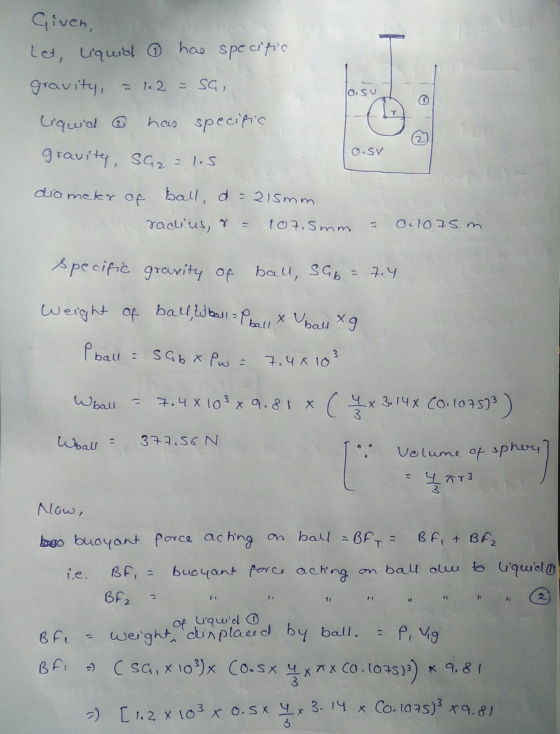
The solid steel ball shown in the figure is submerged between the interface of two liquids with sg of 1.2 and 1.5. The ball has a diameter of 215 mm and specific gravity of 7.4 and is attached by a rope. Note: The interface of the two liquids coincides the center of the sphere.

Determine the buoyant force acting on the ball in N.
Homework Answers
Hope it helps.
Positive rating will be helpful

Add Answer to:
The solid steel ball shown in the figure is submerged between
the interface of two liquids...
The figure shows a transmission shaft. The steel solid shaft is 200 mm long between self-aligning...
 The figure shows a transmission shaft. The steel solid shaft is 200 mm long between self-aligning bearings at A and B. Belt forces (in the same horizontal direction) are applied to a 120-mm diameter sheave at C. The left end of the shaft is connected to an electric motor attached to a clutch by means of a flexible coupling. Nothing is attached to the right end (it is free). Assuming the shaft has a constant diameter, d, (a) Perform the...
Q3) An inclined manometer tube is connected to two closed tanks as shown in the figure...
 Q3) An inclined manometer tube is connected to two closed tanks as shown in the figure below where !-210 cm. A gage was used to measure the pressure at the center of tank A and the reading was 60 kPa. A barometer locates near the tanks reads 72 cm of mercury. Specific weight of water is 9.81 kN/m3 and specific gravity (SG) of mercury is 13.6. a) Find the gage pressure in the center of tank B. b) Find the...
Question 1 Time Allowed: 2 hours The figure shows a transmission shaft. The steel solid shaft...
 Question 1 Time Allowed: 2 hours The figure shows a transmission shaft. The steel solid shaft is 200 mm long between self-aligning bearings at A and B. Belt forces (in the same horizontal direction) are applied to a 120-mm diameter sheave at C. The left end of the shaft is connected to an electric motor attached to a clutch by means of a flexible coupling. Nothing is attach to the right end (it is free). Assuming the shaft has a...
The figure shows a transmission shaft. The steel solid shaft is 200 mm long between self-aligning...
 The figure shows a transmission shaft. The steel solid shaft is 200 mm long between self-aligning bearings at A and B. Belt forces in the same horizontal direction) are applied to a 120-mm diameter sheave at C. The left end of the shaft is connected to an electric motor attached to a clutch by means of a flexible coupling. Nothing is attached to the right end (it is free). Assuming the shaft has a constant diameter, d. (a) Perform the...
The 40 mm diameter shaft made of steel supported at A and B are subject to two loads acting on the direction shown in the figure below.
 The 40 mm diameter shaft made of steel supported at A and B are
subject to two loads acting on the direction shown in the figure
below. Determine the absolute maximum bending stress
developed.
The 40 mm diameter shaft made of steel supported at A and B are
subject to two loads acting on the direction shown in the figure
below. Determine the absolute maximum bending stress
developed.
P6.042 The composite shaft shown in the figure consists of two steel pipes that are connected...
 P6.042 The composite shaft shown in the figure consists of two steel pipes that are connected at flange B and securely attached to rigid walls at A and C. Steel pipe (1) has an outside diameter of 173 mm and a wall thickness of 6 mm. Steel pipe (2) has an outside diameter of 101 mm and a wall thickness of 7 mm. Both pipes are 3.4 m long and have a shear modulus of 80 GPa. If a concentrated...
Figure 3 4. Figure 4 shows a 1.5 in diameter shaft supported by self-aligning ball bearings A and B. There are two chai...
 Figure 3 4. Figure 4 shows a 1.5 in diameter shaft supported by self-aligning ball bearings A and B. There are two chain sprockets, which are attached to the shaft and loaded as shown. Determine the force F. Model this shaft as a simply supported beam. Determine the bearing reactions RA and RB. (OC: A, E), (Ans: RA 1083.3, RB 1916.67 lb,) SHAFT SPROCKET # \ SPROc KET+#2 2 in, 2000 lb 3 in. 4 in. Sin
Figure 3 4....
Figure 3 4. Figure 4 shows a 1.5 in diameter shaft supported by self-aligning ball bearings A and B. There are two chain sprockets, which are attached to the shaft and loaded as shown. Determine the force F. Model this shaft as a simply supported beam. Determine the bearing reactions RA and RB. (OC: A, E), (Ans: RA 1083.3, RB 1916.67 lb,) SHAFT SPROCKET # \ SPROc KET+#2 2 in, 2000 lb 3 in. 4 in. Sin
Figure 3 4....
can you help me figure out the following: part a: Calculate the specific gravity for aluminum...
 can you help me figure out the following:
part a: Calculate the specific gravity for aluminum and for
brass.
part b: Calculate the specific gravity for cork.
part c: Calculate the specific gravity of the isopropyl
alcohol.
Experiment 9 Specific Gravity (Archimedes Principle) Read the Theory section on pages 9-2 & 9-3. Specific gravity is defined as the density (mass per unit volume) of a substance relative to the density of (liquid) water: s p/po, where pe is the density...
can you help me figure out the following:
part a: Calculate the specific gravity for aluminum and for
brass.
part b: Calculate the specific gravity for cork.
part c: Calculate the specific gravity of the isopropyl
alcohol.
Experiment 9 Specific Gravity (Archimedes Principle) Read the Theory section on pages 9-2 & 9-3. Specific gravity is defined as the density (mass per unit volume) of a substance relative to the density of (liquid) water: s p/po, where pe is the density...
A gear reduction unit uses the countershaft shown in the figure. The solid steel shaft is...
 A gear reduction unit uses the countershaft shown in the figure. The solid steel shaft is simply supported by bearings at points O and C. Gear A receives power from another gear with the transmitted force FA applied at the 200 pressure angle as shown. The power is transmitted through the shaft and delivered through gear B through a transmitted force Fa at the pressure angle shown. 0 350 mm 225 ma Gear A 500-mm dia Gear B 200 mm...
The assembly shown in the figure below consists of a thin rod of length l = 23.9 cm and mass m = 1.20 kg with a solid ball of diameter d = 10.0 cm and mass M = 2.00 kg attached to its top.
 The assembly shown in the figure below consists of a thin rod of length l = 23.9 cm and mass m = 1.20 kg with a solid ball of diameter d = 10.0 cm and mass M = 2.00 kg attached to its top. The assembly is free to pivot about a frictionless axle through the bottom of the rod. The assembly is initially vertical and at rest when it starts to rotate clockwise. (a) After the combination rotates through 90...
 The figure shows a transmission shaft. The steel solid shaft is 200 mm long between self-aligning bearings at A and B. Belt forces (in the same horizontal direction) are applied to a 120-mm diameter sheave at C. The left end of the shaft is connected to an electric motor attached to a clutch by means of a flexible coupling. Nothing is attached to the right end (it is free). Assuming the shaft has a constant diameter, d, (a) Perform the...
 Q3) An inclined manometer tube is connected to two closed tanks as shown in the figure below where !-210 cm. A gage was used to measure the pressure at the center of tank A and the reading was 60 kPa. A barometer locates near the tanks reads 72 cm of mercury. Specific weight of water is 9.81 kN/m3 and specific gravity (SG) of mercury is 13.6. a) Find the gage pressure in the center of tank B. b) Find the...
 Question 1 Time Allowed: 2 hours The figure shows a transmission shaft. The steel solid shaft is 200 mm long between self-aligning bearings at A and B. Belt forces (in the same horizontal direction) are applied to a 120-mm diameter sheave at C. The left end of the shaft is connected to an electric motor attached to a clutch by means of a flexible coupling. Nothing is attach to the right end (it is free). Assuming the shaft has a...
 The figure shows a transmission shaft. The steel solid shaft is 200 mm long between self-aligning bearings at A and B. Belt forces in the same horizontal direction) are applied to a 120-mm diameter sheave at C. The left end of the shaft is connected to an electric motor attached to a clutch by means of a flexible coupling. Nothing is attached to the right end (it is free). Assuming the shaft has a constant diameter, d. (a) Perform the...
 The 40 mm diameter shaft made of steel supported at A and B are
subject to two loads acting on the direction shown in the figure
below. Determine the absolute maximum bending stress
developed.
The 40 mm diameter shaft made of steel supported at A and B are
subject to two loads acting on the direction shown in the figure
below. Determine the absolute maximum bending stress
developed.
 P6.042 The composite shaft shown in the figure consists of two steel pipes that are connected at flange B and securely attached to rigid walls at A and C. Steel pipe (1) has an outside diameter of 173 mm and a wall thickness of 6 mm. Steel pipe (2) has an outside diameter of 101 mm and a wall thickness of 7 mm. Both pipes are 3.4 m long and have a shear modulus of 80 GPa. If a concentrated...
 Figure 3 4. Figure 4 shows a 1.5 in diameter shaft supported by self-aligning ball bearings A and B. There are two chain sprockets, which are attached to the shaft and loaded as shown. Determine the force F. Model this shaft as a simply supported beam. Determine the bearing reactions RA and RB. (OC: A, E), (Ans: RA 1083.3, RB 1916.67 lb,) SHAFT SPROCKET # \ SPROc KET+#2 2 in, 2000 lb 3 in. 4 in. Sin
Figure 3 4....
Figure 3 4. Figure 4 shows a 1.5 in diameter shaft supported by self-aligning ball bearings A and B. There are two chain sprockets, which are attached to the shaft and loaded as shown. Determine the force F. Model this shaft as a simply supported beam. Determine the bearing reactions RA and RB. (OC: A, E), (Ans: RA 1083.3, RB 1916.67 lb,) SHAFT SPROCKET # \ SPROc KET+#2 2 in, 2000 lb 3 in. 4 in. Sin
Figure 3 4....
 can you help me figure out the following:
part a: Calculate the specific gravity for aluminum and for
brass.
part b: Calculate the specific gravity for cork.
part c: Calculate the specific gravity of the isopropyl
alcohol.
Experiment 9 Specific Gravity (Archimedes Principle) Read the Theory section on pages 9-2 & 9-3. Specific gravity is defined as the density (mass per unit volume) of a substance relative to the density of (liquid) water: s p/po, where pe is the density...
can you help me figure out the following:
part a: Calculate the specific gravity for aluminum and for
brass.
part b: Calculate the specific gravity for cork.
part c: Calculate the specific gravity of the isopropyl
alcohol.
Experiment 9 Specific Gravity (Archimedes Principle) Read the Theory section on pages 9-2 & 9-3. Specific gravity is defined as the density (mass per unit volume) of a substance relative to the density of (liquid) water: s p/po, where pe is the density...
 A gear reduction unit uses the countershaft shown in the figure. The solid steel shaft is simply supported by bearings at points O and C. Gear A receives power from another gear with the transmitted force FA applied at the 200 pressure angle as shown. The power is transmitted through the shaft and delivered through gear B through a transmitted force Fa at the pressure angle shown. 0 350 mm 225 ma Gear A 500-mm dia Gear B 200 mm...
Most questions answered within 3 hours.
-
Where is the error in this code sequence?
String s1 = "Hello";
String s2 = "ello";...
asked 10 months ago -
Financial data for Joel de Paris, Inc., for last year
follow:
Joel de Paris, Inc.
Balance...
asked 10 months ago -
Consider this reaction:
Al2(SO4)3 (aq)+ BaCl3
(aq) Al2Cl6 (aq)- +
3BaSO4(s) . What is the...
asked 10 months ago -
Suppose that Savneet is considering increasing her
recent random sample from 20 car rentals to 40...
asked 10 months ago -
Trucks arrive at an unloading terminal at an average rate of 120
per hour.
Trucks arrive...
asked 10 months ago -
Why are methanol and ethanol completely soluble in water while
octanol is not very little soluble....
asked 10 months ago -
A facilities manager at a university reads in a research report
that the mean amount of...
asked 10 months ago -
When the CuSO4 is rehydrated by adding water to the anhydrous
compound, is this an endothermic...
asked 10 months ago -
A ray of sunlight is passing from diamond into crown glass; the
angle of incidence is...
asked 10 months ago -
A block of mass 0.249 kg is placed on top of a light, vertical
spring of...
asked 10 months ago -
how do the kidneys compensate in the presences of acidosis
a) trigger hyperventilate
b) reserve acid...
asked 10 months ago -
Question 501 pts
The rental rate of capital to the firm increases. Which of the
following...
asked 10 months ago