
Homework Answers
Solution:
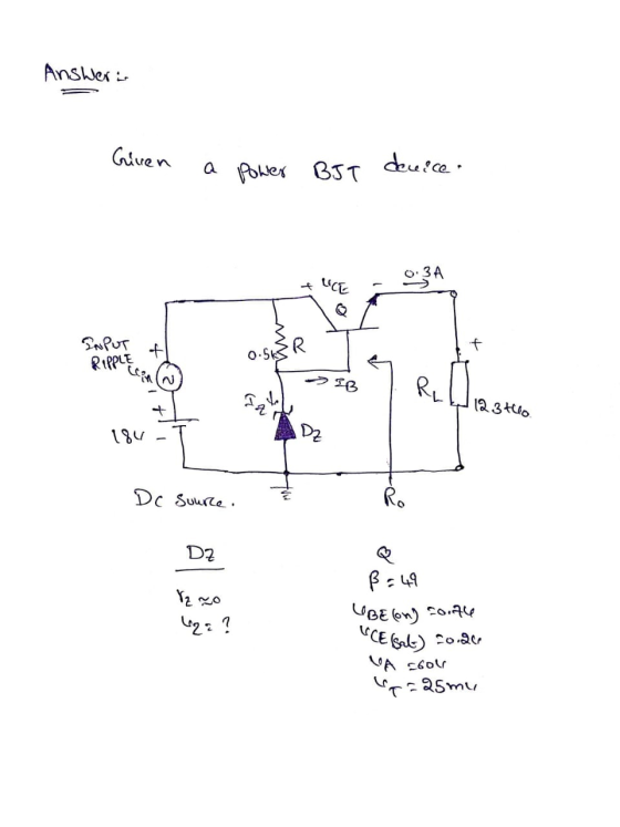
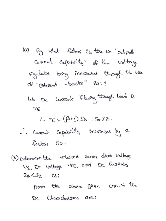
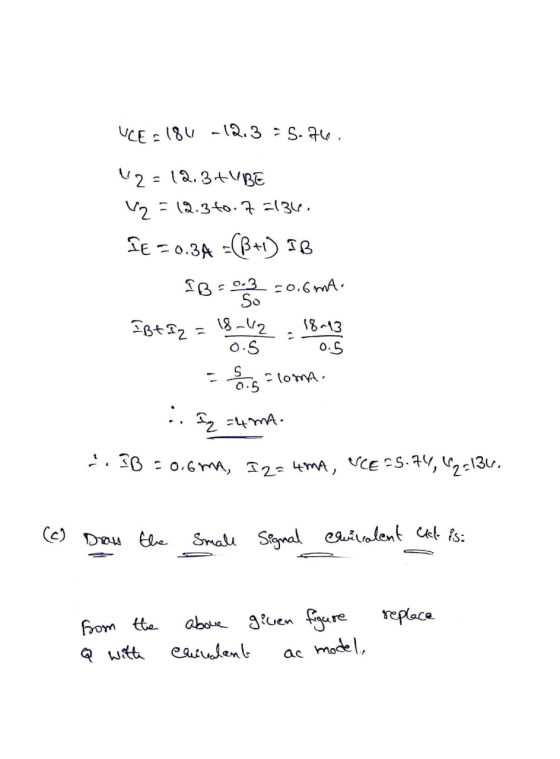
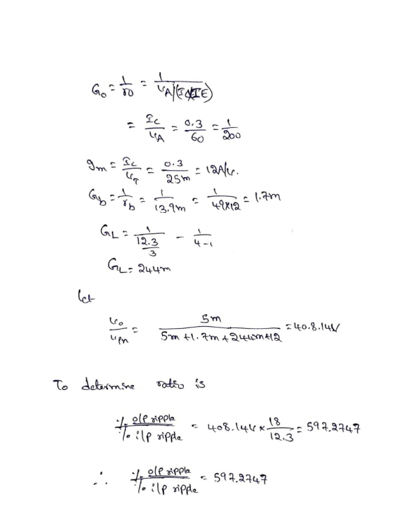
![(d) Determine coltage Source the abole same ckt is taken win is grounded. fit 2 et = 44 (z tamtho] Rip = L = ab tgimthe Rim -](http://img.homeworklib.com/questions/b1da81b0-f609-11eb-ab8d-33865a93a6ef.png?x-oss-process=image/resize,w_560)
![DC input power = 18 x 3in De output power = 18 [lomto.3] ud XIE 512.3 X0.3 12.3X0.3 7 Efficiency = -xloo 18 1oth to:3] :. l.E](http://img.homeworklib.com/questions/b2730230-f609-11eb-86bf-2f580adeeb00.png?x-oss-process=image/resize,w_560)
Add Answer to:
Problem 14) : An "enhanced" Voituge Regulator' with a BTT "Current Booster". By crocling to it...
3. For the regulated power supply shown in Figure 5-3, which is a full-wave bridge rectifier...
 3. For the regulated power supply shown in Figure 5-3, which is a full-wave bridge rectifier containing ter combined with a Zener diode voltage regulator, determine the load voltage VI, load current Ir, source current Is, Zener current Iz and the ripple voltage at the input and output of the regulator, and r(p-p)y respectively, and the ripple frequency fr a fil- VL Ir. Is Iz=. (d-4)1a Ur(p-P) Is V' 1N4002GP Vout = VL + Iz IL 100 V2 120 V...
Design a voltage regulator with zener, so that 7% of the total current flows through the...
Design a voltage regulator with zener, so that 7% of the total current flows through the zener. The zener is 8V and the source is 13V. Determine the values for RS and RL
A boost regulator has an input voltage of Vs = 5V. The average output voltage Va=...
 A boost regulator has an input voltage of Vs = 5V. The average output voltage Va= 15 V and the average load current la = 0.5A. The switching frequency is 25 KHz. If L = 0.15 mH and C = 220uF. Determine: the duty factor, the ripple current of inductor, the peak current inductor, the ripple voltage of filter capacitance, the critical values of L. Plot the waveforms for the source current, inductor current, filter capacitor current, capacitance voltage, and...
that's all information it gives A zener-diode voltage regulator circuit is shown below. The tage V 8.0V and the zener resistance is assumed to Problem 3: (20 points) zener diode has breakdown...
 that's all information it gives
A zener-diode voltage regulator circuit is shown below. The tage V 8.0V and the zener resistance is assumed to Problem 3: (20 points) zener diode has breakdown vol be 0 ohms. The power supply voltage Vps can vary between resistance RL can vary between 100 ohms and 1 kohm. 10V and 14V and the load Ri PS 1. Find a value of Ri such that the zener diode remains properly biased over the range of...
that's all information it gives
A zener-diode voltage regulator circuit is shown below. The tage V 8.0V and the zener resistance is assumed to Problem 3: (20 points) zener diode has breakdown vol be 0 ohms. The power supply voltage Vps can vary between resistance RL can vary between 100 ohms and 1 kohm. 10V and 14V and the load Ri PS 1. Find a value of Ri such that the zener diode remains properly biased over the range of...
(a) The following circuit shows a linear voltage regulator. Assuming the zener diode has specifications (VZ = 2.5 V, IZ...
 (a) The following circuit shows a linear
voltage regulator. Assuming the zener diode has specifications (VZ
= 2.5 V, IZ = 60 mA), select adequate resistor values to provide a
regulated output voltage Vo = 10 V from an unregulated voltage Vi =
15V.
(b) Calculate the power efficiency of the
regulator when a load RL = 10Ω is connected to the regulator
output.
(c) Briefly explain the terms “dropout”, “line
regulation”, and “load regulation”, as they apply to voltage...
(a) The following circuit shows a linear
voltage regulator. Assuming the zener diode has specifications (VZ
= 2.5 V, IZ = 60 mA), select adequate resistor values to provide a
regulated output voltage Vo = 10 V from an unregulated voltage Vi =
15V.
(b) Calculate the power efficiency of the
regulator when a load RL = 10Ω is connected to the regulator
output.
(c) Briefly explain the terms “dropout”, “line
regulation”, and “load regulation”, as they apply to voltage...
It is required to use a FULL-wave rectifier to design a dc power supply that provides...
It is required to use a FULL-wave rectifier to design a dc power supply that provides an average dc output voltage of 15 V. A maximum ripple voltage of ±1 V is allowed on the output voltage. The output voltage will feed a load resistance of 250 Ω. Assume a sinusoidal input voltage with the frequency of 60 Hz. Do not include a Zener diode in your design. (Assume V_D0)* = 0.7 V). a) Draw the circuit diagram. b) Calculate...
Even just steps/formula on what to follow would be sufficient if you cannot complete the question.
 Even just steps/formula on what to follow would be sufficient if
you cannot complete the question.
Draw a bridge rectifier fed from a single-phase 240-V (Au) supply with a 4:1 step down transformer. A 10-2 load is connected to the output. Assume a simplified model for the diodes with VoN 1V per diode and zero leakage current. (a) Draw voltage, current and p(t) waveforms for one diode. (b) Derive the diode voltage spec from the voltage waveforms, and add 50%...
Even just steps/formula on what to follow would be sufficient if
you cannot complete the question.
Draw a bridge rectifier fed from a single-phase 240-V (Au) supply with a 4:1 step down transformer. A 10-2 load is connected to the output. Assume a simplified model for the diodes with VoN 1V per diode and zero leakage current. (a) Draw voltage, current and p(t) waveforms for one diode. (b) Derive the diode voltage spec from the voltage waveforms, and add 50%...
Answer all the questions, please. 1) 2) In the circuit below, if VB1 = 1.3V and...
 Answer all the questions, please.
1)
2)
In the circuit below, if VB1 = 1.3V and VB2 = 2.3V, what is the maximum possible value of the output voltage v? Assume a drop of 0.7V across the diodes when forward-biased. Enter your answer in volts. DÝ D2 VBI = Von The circuit below shows a linear regulator. Assume the unregulated input voltage is Vin = 18 V, the Zener specs are (Vz = 5.1 V. Iz = 50 mA), R1...
Answer all the questions, please.
1)
2)
In the circuit below, if VB1 = 1.3V and VB2 = 2.3V, what is the maximum possible value of the output voltage v? Assume a drop of 0.7V across the diodes when forward-biased. Enter your answer in volts. DÝ D2 VBI = Von The circuit below shows a linear regulator. Assume the unregulated input voltage is Vin = 18 V, the Zener specs are (Vz = 5.1 V. Iz = 50 mA), R1...
power Electronics. Please help Problem 4: (30 points) rect d(r) In the PFC converter shown above,...
 power Electronics. Please help
Problem 4: (30 points) rect d(r) In the PFC converter shown above, the DC value of the output voltage is to be regulated at 200 v and the input ac voltage is vs _ 170 sin(2π 60t) V . The output power is 1 kw. Assume steady-state operation and a switching frequency of 200 kHz. (a) Calculate the inductance needed to limit the maximum peak-peak switching frequency ripple in inductor current to 1.2 A. (b) Calculate...
power Electronics. Please help
Problem 4: (30 points) rect d(r) In the PFC converter shown above, the DC value of the output voltage is to be regulated at 200 v and the input ac voltage is vs _ 170 sin(2π 60t) V . The output power is 1 kw. Assume steady-state operation and a switching frequency of 200 kHz. (a) Calculate the inductance needed to limit the maximum peak-peak switching frequency ripple in inductor current to 1.2 A. (b) Calculate...
Design a FULL WAVE BRIDGE RECTIFIER circuit that will: Take 120volts ac, 60 hz, sinusoidal waveform...
 Design a FULL WAVE BRIDGE RECTIFIER circuit that will:
Take 120volts ac, 60 hz, sinusoidal waveform and convert
it to a “regulated “dc value
giving 12 volts +, - 1 volt across a 2000-ohm output
load resistor with no more than 2%
ripple voltage.
You may assume:
a. An ideal power transformer as discussed in class.
b. For hand computations, you must assume a diode given by
Figure 4.8 page 185.
c. A filter capacitor sized per the textbook equation...
Design a FULL WAVE BRIDGE RECTIFIER circuit that will:
Take 120volts ac, 60 hz, sinusoidal waveform and convert
it to a “regulated “dc value
giving 12 volts +, - 1 volt across a 2000-ohm output
load resistor with no more than 2%
ripple voltage.
You may assume:
a. An ideal power transformer as discussed in class.
b. For hand computations, you must assume a diode given by
Figure 4.8 page 185.
c. A filter capacitor sized per the textbook equation...
 3. For the regulated power supply shown in Figure 5-3, which is a full-wave bridge rectifier containing ter combined with a Zener diode voltage regulator, determine the load voltage VI, load current Ir, source current Is, Zener current Iz and the ripple voltage at the input and output of the regulator, and r(p-p)y respectively, and the ripple frequency fr a fil- VL Ir. Is Iz=. (d-4)1a Ur(p-P) Is V' 1N4002GP Vout = VL + Iz IL 100 V2 120 V...
 A boost regulator has an input voltage of Vs = 5V. The average output voltage Va= 15 V and the average load current la = 0.5A. The switching frequency is 25 KHz. If L = 0.15 mH and C = 220uF. Determine: the duty factor, the ripple current of inductor, the peak current inductor, the ripple voltage of filter capacitance, the critical values of L. Plot the waveforms for the source current, inductor current, filter capacitor current, capacitance voltage, and...
 that's all information it gives
A zener-diode voltage regulator circuit is shown below. The tage V 8.0V and the zener resistance is assumed to Problem 3: (20 points) zener diode has breakdown vol be 0 ohms. The power supply voltage Vps can vary between resistance RL can vary between 100 ohms and 1 kohm. 10V and 14V and the load Ri PS 1. Find a value of Ri such that the zener diode remains properly biased over the range of...
that's all information it gives
A zener-diode voltage regulator circuit is shown below. The tage V 8.0V and the zener resistance is assumed to Problem 3: (20 points) zener diode has breakdown vol be 0 ohms. The power supply voltage Vps can vary between resistance RL can vary between 100 ohms and 1 kohm. 10V and 14V and the load Ri PS 1. Find a value of Ri such that the zener diode remains properly biased over the range of...
 (a) The following circuit shows a linear
voltage regulator. Assuming the zener diode has specifications (VZ
= 2.5 V, IZ = 60 mA), select adequate resistor values to provide a
regulated output voltage Vo = 10 V from an unregulated voltage Vi =
15V.
(b) Calculate the power efficiency of the
regulator when a load RL = 10Ω is connected to the regulator
output.
(c) Briefly explain the terms “dropout”, “line
regulation”, and “load regulation”, as they apply to voltage...
(a) The following circuit shows a linear
voltage regulator. Assuming the zener diode has specifications (VZ
= 2.5 V, IZ = 60 mA), select adequate resistor values to provide a
regulated output voltage Vo = 10 V from an unregulated voltage Vi =
15V.
(b) Calculate the power efficiency of the
regulator when a load RL = 10Ω is connected to the regulator
output.
(c) Briefly explain the terms “dropout”, “line
regulation”, and “load regulation”, as they apply to voltage...
 Even just steps/formula on what to follow would be sufficient if
you cannot complete the question.
Draw a bridge rectifier fed from a single-phase 240-V (Au) supply with a 4:1 step down transformer. A 10-2 load is connected to the output. Assume a simplified model for the diodes with VoN 1V per diode and zero leakage current. (a) Draw voltage, current and p(t) waveforms for one diode. (b) Derive the diode voltage spec from the voltage waveforms, and add 50%...
Even just steps/formula on what to follow would be sufficient if
you cannot complete the question.
Draw a bridge rectifier fed from a single-phase 240-V (Au) supply with a 4:1 step down transformer. A 10-2 load is connected to the output. Assume a simplified model for the diodes with VoN 1V per diode and zero leakage current. (a) Draw voltage, current and p(t) waveforms for one diode. (b) Derive the diode voltage spec from the voltage waveforms, and add 50%...
 Answer all the questions, please.
1)
2)
In the circuit below, if VB1 = 1.3V and VB2 = 2.3V, what is the maximum possible value of the output voltage v? Assume a drop of 0.7V across the diodes when forward-biased. Enter your answer in volts. DÝ D2 VBI = Von The circuit below shows a linear regulator. Assume the unregulated input voltage is Vin = 18 V, the Zener specs are (Vz = 5.1 V. Iz = 50 mA), R1...
Answer all the questions, please.
1)
2)
In the circuit below, if VB1 = 1.3V and VB2 = 2.3V, what is the maximum possible value of the output voltage v? Assume a drop of 0.7V across the diodes when forward-biased. Enter your answer in volts. DÝ D2 VBI = Von The circuit below shows a linear regulator. Assume the unregulated input voltage is Vin = 18 V, the Zener specs are (Vz = 5.1 V. Iz = 50 mA), R1...
 power Electronics. Please help
Problem 4: (30 points) rect d(r) In the PFC converter shown above, the DC value of the output voltage is to be regulated at 200 v and the input ac voltage is vs _ 170 sin(2π 60t) V . The output power is 1 kw. Assume steady-state operation and a switching frequency of 200 kHz. (a) Calculate the inductance needed to limit the maximum peak-peak switching frequency ripple in inductor current to 1.2 A. (b) Calculate...
power Electronics. Please help
Problem 4: (30 points) rect d(r) In the PFC converter shown above, the DC value of the output voltage is to be regulated at 200 v and the input ac voltage is vs _ 170 sin(2π 60t) V . The output power is 1 kw. Assume steady-state operation and a switching frequency of 200 kHz. (a) Calculate the inductance needed to limit the maximum peak-peak switching frequency ripple in inductor current to 1.2 A. (b) Calculate...
 Design a FULL WAVE BRIDGE RECTIFIER circuit that will:
Take 120volts ac, 60 hz, sinusoidal waveform and convert
it to a “regulated “dc value
giving 12 volts +, - 1 volt across a 2000-ohm output
load resistor with no more than 2%
ripple voltage.
You may assume:
a. An ideal power transformer as discussed in class.
b. For hand computations, you must assume a diode given by
Figure 4.8 page 185.
c. A filter capacitor sized per the textbook equation...
Design a FULL WAVE BRIDGE RECTIFIER circuit that will:
Take 120volts ac, 60 hz, sinusoidal waveform and convert
it to a “regulated “dc value
giving 12 volts +, - 1 volt across a 2000-ohm output
load resistor with no more than 2%
ripple voltage.
You may assume:
a. An ideal power transformer as discussed in class.
b. For hand computations, you must assume a diode given by
Figure 4.8 page 185.
c. A filter capacitor sized per the textbook equation...
Most questions answered within 3 hours.
-
Where is the error in this code sequence?
String s1 = "Hello";
String s2 = "ello";...
asked 11 months ago -
Financial data for Joel de Paris, Inc., for last year
follow:
Joel de Paris, Inc.
Balance...
asked 11 months ago -
Consider this reaction:
Al2(SO4)3 (aq)+ BaCl3
(aq) Al2Cl6 (aq)- +
3BaSO4(s) . What is the...
asked 11 months ago -
Suppose that Savneet is considering increasing her
recent random sample from 20 car rentals to 40...
asked 11 months ago -
Trucks arrive at an unloading terminal at an average rate of 120
per hour.
Trucks arrive...
asked 11 months ago -
Why are methanol and ethanol completely soluble in water while
octanol is not very little soluble....
asked 11 months ago -
A facilities manager at a university reads in a research report
that the mean amount of...
asked 11 months ago -
When the CuSO4 is rehydrated by adding water to the anhydrous
compound, is this an endothermic...
asked 11 months ago -
A ray of sunlight is passing from diamond into crown glass; the
angle of incidence is...
asked 11 months ago -
A block of mass 0.249 kg is placed on top of a light, vertical
spring of...
asked 11 months ago -
how do the kidneys compensate in the presences of acidosis
a) trigger hyperventilate
b) reserve acid...
asked 11 months ago -
Question 501 pts
The rental rate of capital to the firm increases. Which of the
following...
asked 11 months ago