Answer all parts and show all work.
Homework Answers




Add Answer to:
Answer all parts and show all work.
Design a Pl or PDcontroller for the system Go)+...
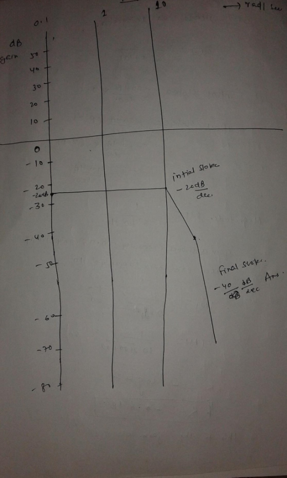
3. Design a PI or PD controller for the system G(8) = s(s+10) to meet the...
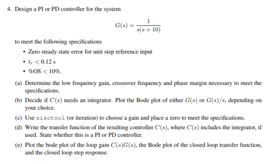
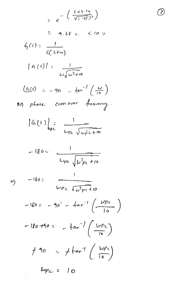
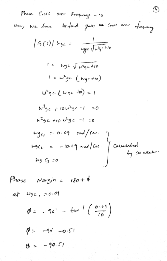
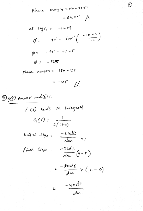
 3. Design a PI or PD controller for the system G(8) = s(s+10) to meet the following specifications • Zero steady state error for unit step reference input • tr< 0.12 - . %OS < 10%. (a) Determine the low frequency gain, crossover frequency and phase margin necessary to meet the specifications. (b) Decide if C(s) needs an integrator. Plot the Bode plot of either G(s) or G(s)/s, depending on your choice. (c) Use sisotool (or iteration) to choose a...
4. You want to design an orientation controller for a satellite system whose thrusters provide a...
 4. You want to design an orientation controller for a satellite system whose thrusters provide a torque T to modify the angular position 0 with transfer function (s) 0.1 G(s) T(s) $2 Y() R(s) G(s) C(s) You want to add damping to the system to minimize any oscillations (%OS < 5%) but still maintain a 1% settling time of less than 60 s to a unit step input. I(a) Sketch the allowable pole locations in the complex plane to meet...
Consider the unity-feedback system shown below: R(s) E(s) input: r(t), output: y(t) C(s) P(s) error: e()...
 Consider the unity-feedback system shown below: R(s) E(s) input: r(t), output: y(t) C(s) P(s) error: e() r(t) y(t) closed-loop transfer-function: Hyr(sD t the closed-loop transfer-function be Hyr(s) Y (s) R(s) Let the transfer-function of the plant be P(s) 10 s (s 1) (s 5) The open-loop transfer-function is G(s) P(s) C(s) DESIGN OBJECTIVES: Find a controller C(s) such that the following are satisfied i) The closed-loop system is stable. ii) The steady-state error ess due to a unit-ramp input r(t)...
Spring 2019 3. Given a closed-loop control system with unity feedback is shown in the block...
 Spring 2019 3. Given a closed-loop control system with unity feedback is shown in the block diagram. G(s) is the open-loop transfer function, and the controller is a gain, K. 1. (20) Calculate the open-loop transfer function tar →Q--t G(s) (10) Calculate the steady-state error to a step input of the open-loop system. 7. (in Bode Form) from the Bode plot. (10) Calculate the shortest possible settling time with a percentage overshoot of 5% or less. 8. 2. (10)Plot the...
Consider the system shown as below. Draw a Bode diagram of the open-loop transfer function G(s).
 1 Consider the system shown as below. Draw a Bode diagram of the open-loop transfer function G(s). Determine the phase margin, gain-crossover frequency, gain margin and phase-crossover frequency, (Sketch the bode diagram by hand) 2 Consider the system shown as below. Use MATLAB to draw a bode diagram of the open-loop transfer function G(s). Show the gain-crossover frequency and phase-crossover frequency in the Bode diagram and determine the phase margin and gain margin. 3. Consider the system shown as below. Design a...
G) r(t) Figure 1: Feedback control system A pulley and belt transmission has a linearized relationship between the driven pulley angle θ(t) in degrees and the input torque u(t) in Newton meters given...
 G) r(t) Figure 1: Feedback control system A pulley and belt transmission has a linearized relationship between the driven pulley angle θ(t) in degrees and the input torque u(t) in Newton meters given by the following differential equation du(t) A feedback control system (illustrated in Figure 1) needs to be designed such that the closed-loop system is asymptotically stable and such that the following design criteria are met: 1. the gain crossover frequency a should be between and a 2....
Prob. 5 (30 pts): You are to design a compensator for a radar antenna as shown...
 Prob. 5 (30 pts): You are to design a compensator for a radar antenna as shown below. Determine G. (s) so that (a)* The closed-loop system has a bandwidth of approximately 20 rad/s. (b) The closed loop system must have positive phase margin. (6) Increase the attenuation at 200 rad/sec or higher. *You can assume that the bandwidth of the closed system is equal to the gain crossover frequency of the open loop system. You may wish to use the...
Please help as much as you can, I want to use this probem as a study guide for the final so any and all help / code is super appreciatted. Thanks Consider a simple direct current motor with transfer...
 Please help as much as you can, I want to use this probem as a
study guide for the final so any and all help / code is super
appreciatted. Thanks
Consider a simple direct current motor with transfer function 10 P(s) = 2s2+s (a) Plot a Bode plot for the plant's transfer function. (b) Design a PD-controller that gives a closed loop bandwidth, wBw, of at least 10 rad/sec and has a phase margin of at least 30°· Using...
Please help as much as you can, I want to use this probem as a
study guide for the final so any and all help / code is super
appreciatted. Thanks
Consider a simple direct current motor with transfer function 10 P(s) = 2s2+s (a) Plot a Bode plot for the plant's transfer function. (b) Design a PD-controller that gives a closed loop bandwidth, wBw, of at least 10 rad/sec and has a phase margin of at least 30°· Using...
Assignment 3: Frequency Domain Controller Design using Bode-plots 2 Augment the open loop plant G(s) =...
 Assignment 3: Frequency Domain Controller Design using Bode-plots 2 Augment the open loop plant G(s) = RS), with sim- ple feedback an a dynamic compensator to meet the following specifications: (a) a cross over frequency of we 3 [rad/sec] (b) a phase margin better than 45. (c) a steady state error when tracking a step input < 5%. in H(s) G(sRecall that Bode plots are applied to the loop gain. out
Assignment 3: Frequency Domain Controller Design using Bode-plots 10 2 Augment the open loop plant G()...
 Assignment 3: Frequency Domain Controller Design using Bode-plots 10 2 Augment the open loop plant G() +27 with sim ple feedback an a dynamic compensator to meet the following specifications: (a) a cross over frequency of w 3 [rad/sec). (b) a phase margin better than 45o (c) a steady state error when tracking a step input < 5%. in H(s) G(s) Recall that Bode plots are applied to the loop gain. out
 3. Design a PI or PD controller for the system G(8) = s(s+10) to meet the following specifications • Zero steady state error for unit step reference input • tr< 0.12 - . %OS < 10%. (a) Determine the low frequency gain, crossover frequency and phase margin necessary to meet the specifications. (b) Decide if C(s) needs an integrator. Plot the Bode plot of either G(s) or G(s)/s, depending on your choice. (c) Use sisotool (or iteration) to choose a...
 4. You want to design an orientation controller for a satellite system whose thrusters provide a torque T to modify the angular position 0 with transfer function (s) 0.1 G(s) T(s) $2 Y() R(s) G(s) C(s) You want to add damping to the system to minimize any oscillations (%OS < 5%) but still maintain a 1% settling time of less than 60 s to a unit step input. I(a) Sketch the allowable pole locations in the complex plane to meet...
 Consider the unity-feedback system shown below: R(s) E(s) input: r(t), output: y(t) C(s) P(s) error: e() r(t) y(t) closed-loop transfer-function: Hyr(sD t the closed-loop transfer-function be Hyr(s) Y (s) R(s) Let the transfer-function of the plant be P(s) 10 s (s 1) (s 5) The open-loop transfer-function is G(s) P(s) C(s) DESIGN OBJECTIVES: Find a controller C(s) such that the following are satisfied i) The closed-loop system is stable. ii) The steady-state error ess due to a unit-ramp input r(t)...
 Spring 2019 3. Given a closed-loop control system with unity feedback is shown in the block diagram. G(s) is the open-loop transfer function, and the controller is a gain, K. 1. (20) Calculate the open-loop transfer function tar →Q--t G(s) (10) Calculate the steady-state error to a step input of the open-loop system. 7. (in Bode Form) from the Bode plot. (10) Calculate the shortest possible settling time with a percentage overshoot of 5% or less. 8. 2. (10)Plot the...
 G) r(t) Figure 1: Feedback control system A pulley and belt transmission has a linearized relationship between the driven pulley angle θ(t) in degrees and the input torque u(t) in Newton meters given by the following differential equation du(t) A feedback control system (illustrated in Figure 1) needs to be designed such that the closed-loop system is asymptotically stable and such that the following design criteria are met: 1. the gain crossover frequency a should be between and a 2....
 Prob. 5 (30 pts): You are to design a compensator for a radar antenna as shown below. Determine G. (s) so that (a)* The closed-loop system has a bandwidth of approximately 20 rad/s. (b) The closed loop system must have positive phase margin. (6) Increase the attenuation at 200 rad/sec or higher. *You can assume that the bandwidth of the closed system is equal to the gain crossover frequency of the open loop system. You may wish to use the...
 Please help as much as you can, I want to use this probem as a
study guide for the final so any and all help / code is super
appreciatted. Thanks
Consider a simple direct current motor with transfer function 10 P(s) = 2s2+s (a) Plot a Bode plot for the plant's transfer function. (b) Design a PD-controller that gives a closed loop bandwidth, wBw, of at least 10 rad/sec and has a phase margin of at least 30°· Using...
Please help as much as you can, I want to use this probem as a
study guide for the final so any and all help / code is super
appreciatted. Thanks
Consider a simple direct current motor with transfer function 10 P(s) = 2s2+s (a) Plot a Bode plot for the plant's transfer function. (b) Design a PD-controller that gives a closed loop bandwidth, wBw, of at least 10 rad/sec and has a phase margin of at least 30°· Using...
 Assignment 3: Frequency Domain Controller Design using Bode-plots 2 Augment the open loop plant G(s) = RS), with sim- ple feedback an a dynamic compensator to meet the following specifications: (a) a cross over frequency of we 3 [rad/sec] (b) a phase margin better than 45. (c) a steady state error when tracking a step input < 5%. in H(s) G(sRecall that Bode plots are applied to the loop gain. out
 Assignment 3: Frequency Domain Controller Design using Bode-plots 10 2 Augment the open loop plant G() +27 with sim ple feedback an a dynamic compensator to meet the following specifications: (a) a cross over frequency of w 3 [rad/sec). (b) a phase margin better than 45o (c) a steady state error when tracking a step input < 5%. in H(s) G(s) Recall that Bode plots are applied to the loop gain. out
Most questions answered within 3 hours.
-
Where is the error in this code sequence?
String s1 = "Hello";
String s2 = "ello";...
asked 11 months ago -
Financial data for Joel de Paris, Inc., for last year
follow:
Joel de Paris, Inc.
Balance...
asked 11 months ago -
Consider this reaction:
Al2(SO4)3 (aq)+ BaCl3
(aq) Al2Cl6 (aq)- +
3BaSO4(s) . What is the...
asked 11 months ago -
Suppose that Savneet is considering increasing her
recent random sample from 20 car rentals to 40...
asked 11 months ago -
Trucks arrive at an unloading terminal at an average rate of 120
per hour.
Trucks arrive...
asked 11 months ago -
Why are methanol and ethanol completely soluble in water while
octanol is not very little soluble....
asked 11 months ago -
A facilities manager at a university reads in a research report
that the mean amount of...
asked 11 months ago -
When the CuSO4 is rehydrated by adding water to the anhydrous
compound, is this an endothermic...
asked 11 months ago -
A ray of sunlight is passing from diamond into crown glass; the
angle of incidence is...
asked 11 months ago -
A block of mass 0.249 kg is placed on top of a light, vertical
spring of...
asked 11 months ago -
how do the kidneys compensate in the presences of acidosis
a) trigger hyperventilate
b) reserve acid...
asked 11 months ago -
Question 501 pts
The rental rate of capital to the firm increases. Which of the
following...
asked 11 months ago