
Homework Answers


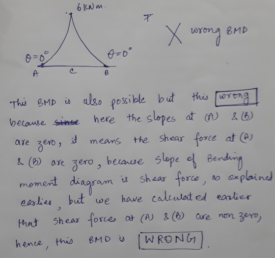
The last page is not the answer. It is just to explain the concept
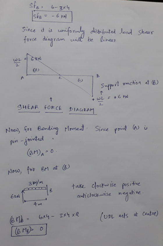
How BMD is drawn.
Add Answer to:
calculate reaction forces at the supports. Draw shear & moment
diagrams to find the critical location....
4. For the following two structures, calculate the reaction forces and draw the shear force diagrams...
 4. For the following two structures, calculate the reaction forces and draw the shear force diagrams and bending moment diagrams 25 kN Hinge 6 m 3 m 6 m Hinge 25 kN 3 m 3 m 3 m 6 m
a). Find the reactions at supports. b). Draw complete shear and moment diagrams for each beam...
 a). Find the reactions at supports. b). Draw complete shear and moment diagrams for each beam c). Label the magnitude and location of absolute maximum values on each shear and moment diagram 500 N/m 150 N/m 0.5m 0.5 m 0.5 m URE P5-30
-find the reaction forces at A & B. -shear and moment diagrams -locate where the shear...
 -find the reaction forces at A & B.
-shear and moment diagrams
-locate where the shear is zero and bending moments are at a
maximum positive and negative. Convert any decimals to closest feet
and inches 1/8 inch.
2.0m (o. o KN 10,0 KN 2.0m 2.om
-find the reaction forces at A & B.
-shear and moment diagrams
-locate where the shear is zero and bending moments are at a
maximum positive and negative. Convert any decimals to closest feet
and inches 1/8 inch.
2.0m (o. o KN 10,0 KN 2.0m 2.om
1- Draw shear and bending moment diagrams for the following simply supported beams, find the location...
 1- Draw shear and bending moment diagrams for the following simply supported beams, find the location and magnitude of maximum moment for each one. Show all of your calculations. 1 kN 4 KN 2 kN (7marks) 5 kN/m TITIT 40 70 70 40 40 60 A B с TI G DE All distances in cm II- 3kN 1.5 kN/m A B с RA 6m 3m Rc
3. Without writing shear and moment equations, draw shear and moment diagrams and indicate the values...
 3. Without writing shear and moment equations, draw shear and moment diagrams and indicate the values at all critical locations. 20 kN 40 kN/m 20 kN/m 1.2m 4m 4m
For the beam shown, draw the shear and moment diagrams and find the magnitude and location of the maximum moment.
 For the beam shown, draw the shear and moment diagrams and find the magnitude and location of the maximum moment.
For the frame shown below: 1- Calculate the reactions at the supports. 2- Draw the Normal force, the Shear force and the Bending moment diagrams. Indicate all critical values 3- Show the equilibrium a...
 For the frame shown below:1- Calculate the reactions at the supports.2- Draw the Normal force, the Shear force and the Bending moment
diagrams. Indicate all critical values3- Show the equilibrium at node B.4- Develop the analytical expression for the normal force, the
shear force and the bending moment diagram for memberBC.The 4 Kips/ft load is applied perpendicular to member
AB.
For the frame shown below:1- Calculate the reactions at the supports.2- Draw the Normal force, the Shear force and the Bending moment
diagrams. Indicate all critical values3- Show the equilibrium at node B.4- Develop the analytical expression for the normal force, the
shear force and the bending moment diagram for memberBC.The 4 Kips/ft load is applied perpendicular to member
AB.
oblem 5 (9 marks) fo thind te reations at the supports 1- Find the reactions at...
 oblem 5 (9 marks) fo thind te reations at the supports 1- Find the reactions at the supports 2- Draw the shear force and bending moment diagrams showing the values at critical sections 3- Locate the section with zero shear and calculate the maximum bending moment 4 kN/m x2-22 几。 22 kN 22 kN 0ヅ 2o ly
Draw the shear and moment diagrams, and provide shear/moment equations for the beam with following parameters:...
 Draw the shear and moment diagrams, and provide shear/moment
equations for the beam with
following parameters: P1 = 30 kN; P2 = 50 kN; a = 1 m; b = 3 m; c =
2 m
Draw the shear and moment diagrams, and provide shear/moment
equations for the beam with
following parameters: P1 = 30 kN; P2 = 50 kN; a = 1 m; b = 3 m; c =
2 m
For the beams of problems 6.2-6.16, draw the shear force and bending moment diagrams and find...
 For the beams of problems 6.2-6.16, draw the shear force and
bending moment
diagrams and find the maximum shear force, maximum bending moment
and
point(s) of contraflexure (PCF).
7 kN 6 kN/m 4 kN/m B 2 m e C D E 24 kN 1,5m 7590.0.751 Figure 6.41
For the beams of problems 6.2-6.16, draw the shear force and
bending moment
diagrams and find the maximum shear force, maximum bending moment
and
point(s) of contraflexure (PCF).
7 kN 6 kN/m 4 kN/m B 2 m e C D E 24 kN 1,5m 7590.0.751 Figure 6.41
 4. For the following two structures, calculate the reaction forces and draw the shear force diagrams and bending moment diagrams 25 kN Hinge 6 m 3 m 6 m Hinge 25 kN 3 m 3 m 3 m 6 m
 a). Find the reactions at supports. b). Draw complete shear and moment diagrams for each beam c). Label the magnitude and location of absolute maximum values on each shear and moment diagram 500 N/m 150 N/m 0.5m 0.5 m 0.5 m URE P5-30
 -find the reaction forces at A & B.
-shear and moment diagrams
-locate where the shear is zero and bending moments are at a
maximum positive and negative. Convert any decimals to closest feet
and inches 1/8 inch.
2.0m (o. o KN 10,0 KN 2.0m 2.om
-find the reaction forces at A & B.
-shear and moment diagrams
-locate where the shear is zero and bending moments are at a
maximum positive and negative. Convert any decimals to closest feet
and inches 1/8 inch.
2.0m (o. o KN 10,0 KN 2.0m 2.om
 1- Draw shear and bending moment diagrams for the following simply supported beams, find the location and magnitude of maximum moment for each one. Show all of your calculations. 1 kN 4 KN 2 kN (7marks) 5 kN/m TITIT 40 70 70 40 40 60 A B с TI G DE All distances in cm II- 3kN 1.5 kN/m A B с RA 6m 3m Rc
 3. Without writing shear and moment equations, draw shear and moment diagrams and indicate the values at all critical locations. 20 kN 40 kN/m 20 kN/m 1.2m 4m 4m
 For the frame shown below:1- Calculate the reactions at the supports.2- Draw the Normal force, the Shear force and the Bending moment
diagrams. Indicate all critical values3- Show the equilibrium at node B.4- Develop the analytical expression for the normal force, the
shear force and the bending moment diagram for memberBC.The 4 Kips/ft load is applied perpendicular to member
AB.
For the frame shown below:1- Calculate the reactions at the supports.2- Draw the Normal force, the Shear force and the Bending moment
diagrams. Indicate all critical values3- Show the equilibrium at node B.4- Develop the analytical expression for the normal force, the
shear force and the bending moment diagram for memberBC.The 4 Kips/ft load is applied perpendicular to member
AB.
 oblem 5 (9 marks) fo thind te reations at the supports 1- Find the reactions at the supports 2- Draw the shear force and bending moment diagrams showing the values at critical sections 3- Locate the section with zero shear and calculate the maximum bending moment 4 kN/m x2-22 几。 22 kN 22 kN 0ヅ 2o ly
 Draw the shear and moment diagrams, and provide shear/moment
equations for the beam with
following parameters: P1 = 30 kN; P2 = 50 kN; a = 1 m; b = 3 m; c =
2 m
Draw the shear and moment diagrams, and provide shear/moment
equations for the beam with
following parameters: P1 = 30 kN; P2 = 50 kN; a = 1 m; b = 3 m; c =
2 m
 For the beams of problems 6.2-6.16, draw the shear force and
bending moment
diagrams and find the maximum shear force, maximum bending moment
and
point(s) of contraflexure (PCF).
7 kN 6 kN/m 4 kN/m B 2 m e C D E 24 kN 1,5m 7590.0.751 Figure 6.41
For the beams of problems 6.2-6.16, draw the shear force and
bending moment
diagrams and find the maximum shear force, maximum bending moment
and
point(s) of contraflexure (PCF).
7 kN 6 kN/m 4 kN/m B 2 m e C D E 24 kN 1,5m 7590.0.751 Figure 6.41
Most questions answered within 3 hours.
-
Where is the error in this code sequence?
String s1 = "Hello";
String s2 = "ello";...
asked 10 months ago -
Financial data for Joel de Paris, Inc., for last year
follow:
Joel de Paris, Inc.
Balance...
asked 10 months ago -
Consider this reaction:
Al2(SO4)3 (aq)+ BaCl3
(aq) Al2Cl6 (aq)- +
3BaSO4(s) . What is the...
asked 10 months ago -
Suppose that Savneet is considering increasing her
recent random sample from 20 car rentals to 40...
asked 10 months ago -
Trucks arrive at an unloading terminal at an average rate of 120
per hour.
Trucks arrive...
asked 10 months ago -
Why are methanol and ethanol completely soluble in water while
octanol is not very little soluble....
asked 10 months ago -
A facilities manager at a university reads in a research report
that the mean amount of...
asked 10 months ago -
When the CuSO4 is rehydrated by adding water to the anhydrous
compound, is this an endothermic...
asked 10 months ago -
A ray of sunlight is passing from diamond into crown glass; the
angle of incidence is...
asked 10 months ago -
A block of mass 0.249 kg is placed on top of a light, vertical
spring of...
asked 10 months ago -
how do the kidneys compensate in the presences of acidosis
a) trigger hyperventilate
b) reserve acid...
asked 10 months ago -
Question 501 pts
The rental rate of capital to the firm increases. Which of the
following...
asked 10 months ago