Solve this circuit using node-voltage method. Determine the currents through all the elements and voltages across all elements. Verify that the total power developed equals the total power absorbed
Without repeating the node-voltage analysis, predict the node
voltages at nodes d, c, b and g, if node a was selected as the
reference node (or ground).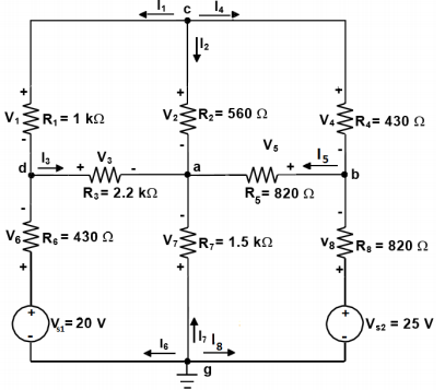
Homework Answers
Request Answer!
We need at least 10 more requests to produce the answer.
0 / 10 have requested this problem solution
The more requests, the faster the answer.
Add Answer to:
Solve this circuit using node-voltage method. Determine the
currents through all the elements and voltages across...
2. (2000) Electromagnetics (DC Circuit) Problem a. Calculate the voltages across all resistors and the currents through all the resistors and voltage sources in the following circuit using Kirchhoff&...
 2. (2000) Electromagnetics (DC Circuit) Problem a. Calculate the voltages across all resistors and the currents through all the resistors and voltage sources in the following circuit using Kirchhoff's junction rule (nodal analysis). Show the directions initially assumed for the junction (node) currents. Use the minimum number of junctions (nodes) necessary to accomplish this b. Calculate the power dissipation in each resistor and the sum (or total) of these individual power dissipation values c. Calculate the power associated with each...
Node Voltage Method Example 4: find v2 1,-24,1-3A, Ri-20,R,-40,R,-20,R,-30 . Label currents and voltages (polarities "arbitrarily"...
 Node Voltage Method Example 4: find v2 1,-24,1-3A, Ri-20,R,-40,R,-20,R,-30 . Label currents and voltages (polarities "arbitrarily" chosen) + R3- 1. 2. Choose Node d (v) as the reference node 3. Define remaining n -1 (3) voltages 2 (Vd 0) Va is independent V, is independent >Ve is independent 4. Apply KCL at nodes a, b, and c 1/27/2019 Node and Mesh Methods
(1) Review materials related to the node voltage method and superposition. (2) Read through the entire...
 (1) Review materials related to the node voltage method and superposition. (2) Read through the entire handout to familiarize yourself with what you will do during lab. (3) Use the node voltage approach to find the voltages at nodes A through E in the circuit of Figure 1. Take Vs1 = 3V, Vs2 = 12V, R1 = 10k2, R2 = 3.3kg, R3 = 1k92, and R4 = 1kg. (4) Bring your prelab to lab. A R1 B R3 NN Vs1...
R 0 Rz 3 + VA R3 + 3 VA Vg + Ig mm HU WW...
 R 0 Rz 3 + VA R3 + 3 VA Vg + Ig mm HU WW Ry you are given: Ri = R2 = Rs = RA 19, V, = 8V and 1, - 8A. a) Draw the graph and identify a tree that satisfies the guidelines (include resistor RA in the tree as well). b) Formulate and solve the node voltage equations in matrix form (stick to the given node numbering!). c) Compute all the powers, and verify that...
Solve each practice problem. TYPE solutions in engineering notation TYPE solutions in engineering notation. Calcula...
 Solve each practice problem. TYPE solutions in
engineering notation
TYPE solutions in engineering
notation.
Calculate the component voltages and branch currents for the circuit shown in Figure 6.40, along with the values of I, and Rr. 3. R3 2 kn R4 4.7 k R1 10 k Vs 26 V R5 3.3 k R2 3 kn FIGURE 6.40 Calculate the component currents and loop voltages for the circuit shown in Figure 6.42, along with the values of I and Rr 5....
Solve each practice problem. TYPE solutions in
engineering notation
TYPE solutions in engineering
notation.
Calculate the component voltages and branch currents for the circuit shown in Figure 6.40, along with the values of I, and Rr. 3. R3 2 kn R4 4.7 k R1 10 k Vs 26 V R5 3.3 k R2 3 kn FIGURE 6.40 Calculate the component currents and loop voltages for the circuit shown in Figure 6.42, along with the values of I and Rr 5....
Learning Goal: To use the node-voltage method to solve circuits that contain resistors and independent sources....
 Learning Goal: To use the node-voltage method to solve circuits that contain resistors and independent sources. The node-voltage method is a general technique for solving circuits. Fundamentally, it involves writing KCL equations at essential nodes. You should review KCL and the definition of an essential node before beginning. In this tutorial, you will use the node-voltage method to find the current through the voltage source, io , and the voltage drop across the 5 kN resistor, vo, for the circuit...
Learning Goal: To use the node-voltage method to solve circuits with branches containing only a voltage...
 Learning Goal: To use the node-voltage method to solve circuits with branches containing only a voltage source. The node-voltage method is a general technique for solving circuits. Fundamentally, it involves writing KCL equations at essential nodes. When the circuit contains a dependent source, you must write a constraint equation for each dependent source, in addition to the KCL equations. When the circuit contains one or more voltage sources that are the only components in branches connecting two essential nodes, the...
Voltage and Current Division For the circuit shown, calculate V. V and Vs when V. =...
 Voltage and Current Division For the circuit shown, calculate V. V and Vs when V. = 7 V, R; = 18 2. R2 = 66 2. R3 = 57 2. R4 = 37 and Rs = 332 Express your answer to two significant figures, with appropriate units View Available Hint(s) @? R-180 R2 = 660 + V + 12 0.597 V = 7 V R3 - 570 V 1.89 V R$ = 33 R = 37 Vs + - V4...
2) Use the circuit below to determine the following: a. Use mesh curre b. Use node-voltage...
 2) Use the circuit below to determine the following: a. Use mesh curre b. Use node-voltage to verify the currents i,- ie from part a. (10 pts) c. Show that th nt to find the branch currents for i,- ie for the circuit shown (10 pts) e total power developed in the circuit equals the total power consumed by the circuit. (5 pts) 5? 102 19 A 40 23ia 2 lb 240 V
Use measured resistance values and node analysis to calculate the node voltages. Use measured resistance values...
 Use measured resistance values and node analysis to calculate
the node voltages.
Use measured resistance values and mesh analysis to calculate
the mesh currents.
Show that the calculated values agree with the measured values
and explain any discrepancies between measured and calculated
values.
Introduction: In this pre-lab we will look at node voltages, mesh currents and bridge circuits. Bridge Circuits are used to make precision measurements, and in this lab -- -0 V2 will look at a DC Bridge Circuit...
Use measured resistance values and node analysis to calculate
the node voltages.
Use measured resistance values and mesh analysis to calculate
the mesh currents.
Show that the calculated values agree with the measured values
and explain any discrepancies between measured and calculated
values.
Introduction: In this pre-lab we will look at node voltages, mesh currents and bridge circuits. Bridge Circuits are used to make precision measurements, and in this lab -- -0 V2 will look at a DC Bridge Circuit...
 2. (2000) Electromagnetics (DC Circuit) Problem a. Calculate the voltages across all resistors and the currents through all the resistors and voltage sources in the following circuit using Kirchhoff's junction rule (nodal analysis). Show the directions initially assumed for the junction (node) currents. Use the minimum number of junctions (nodes) necessary to accomplish this b. Calculate the power dissipation in each resistor and the sum (or total) of these individual power dissipation values c. Calculate the power associated with each...
 Node Voltage Method Example 4: find v2 1,-24,1-3A, Ri-20,R,-40,R,-20,R,-30 . Label currents and voltages (polarities "arbitrarily" chosen) + R3- 1. 2. Choose Node d (v) as the reference node 3. Define remaining n -1 (3) voltages 2 (Vd 0) Va is independent V, is independent >Ve is independent 4. Apply KCL at nodes a, b, and c 1/27/2019 Node and Mesh Methods
 (1) Review materials related to the node voltage method and superposition. (2) Read through the entire handout to familiarize yourself with what you will do during lab. (3) Use the node voltage approach to find the voltages at nodes A through E in the circuit of Figure 1. Take Vs1 = 3V, Vs2 = 12V, R1 = 10k2, R2 = 3.3kg, R3 = 1k92, and R4 = 1kg. (4) Bring your prelab to lab. A R1 B R3 NN Vs1...
 R 0 Rz 3 + VA R3 + 3 VA Vg + Ig mm HU WW Ry you are given: Ri = R2 = Rs = RA 19, V, = 8V and 1, - 8A. a) Draw the graph and identify a tree that satisfies the guidelines (include resistor RA in the tree as well). b) Formulate and solve the node voltage equations in matrix form (stick to the given node numbering!). c) Compute all the powers, and verify that...
 Solve each practice problem. TYPE solutions in
engineering notation
TYPE solutions in engineering
notation.
Calculate the component voltages and branch currents for the circuit shown in Figure 6.40, along with the values of I, and Rr. 3. R3 2 kn R4 4.7 k R1 10 k Vs 26 V R5 3.3 k R2 3 kn FIGURE 6.40 Calculate the component currents and loop voltages for the circuit shown in Figure 6.42, along with the values of I and Rr 5....
Solve each practice problem. TYPE solutions in
engineering notation
TYPE solutions in engineering
notation.
Calculate the component voltages and branch currents for the circuit shown in Figure 6.40, along with the values of I, and Rr. 3. R3 2 kn R4 4.7 k R1 10 k Vs 26 V R5 3.3 k R2 3 kn FIGURE 6.40 Calculate the component currents and loop voltages for the circuit shown in Figure 6.42, along with the values of I and Rr 5....
 Learning Goal: To use the node-voltage method to solve circuits that contain resistors and independent sources. The node-voltage method is a general technique for solving circuits. Fundamentally, it involves writing KCL equations at essential nodes. You should review KCL and the definition of an essential node before beginning. In this tutorial, you will use the node-voltage method to find the current through the voltage source, io , and the voltage drop across the 5 kN resistor, vo, for the circuit...
 Learning Goal: To use the node-voltage method to solve circuits with branches containing only a voltage source. The node-voltage method is a general technique for solving circuits. Fundamentally, it involves writing KCL equations at essential nodes. When the circuit contains a dependent source, you must write a constraint equation for each dependent source, in addition to the KCL equations. When the circuit contains one or more voltage sources that are the only components in branches connecting two essential nodes, the...
 Voltage and Current Division For the circuit shown, calculate V. V and Vs when V. = 7 V, R; = 18 2. R2 = 66 2. R3 = 57 2. R4 = 37 and Rs = 332 Express your answer to two significant figures, with appropriate units View Available Hint(s) @? R-180 R2 = 660 + V + 12 0.597 V = 7 V R3 - 570 V 1.89 V R$ = 33 R = 37 Vs + - V4...
 2) Use the circuit below to determine the following: a. Use mesh curre b. Use node-voltage to verify the currents i,- ie from part a. (10 pts) c. Show that th nt to find the branch currents for i,- ie for the circuit shown (10 pts) e total power developed in the circuit equals the total power consumed by the circuit. (5 pts) 5? 102 19 A 40 23ia 2 lb 240 V
 Use measured resistance values and node analysis to calculate
the node voltages.
Use measured resistance values and mesh analysis to calculate
the mesh currents.
Show that the calculated values agree with the measured values
and explain any discrepancies between measured and calculated
values.
Introduction: In this pre-lab we will look at node voltages, mesh currents and bridge circuits. Bridge Circuits are used to make precision measurements, and in this lab -- -0 V2 will look at a DC Bridge Circuit...
Use measured resistance values and node analysis to calculate
the node voltages.
Use measured resistance values and mesh analysis to calculate
the mesh currents.
Show that the calculated values agree with the measured values
and explain any discrepancies between measured and calculated
values.
Introduction: In this pre-lab we will look at node voltages, mesh currents and bridge circuits. Bridge Circuits are used to make precision measurements, and in this lab -- -0 V2 will look at a DC Bridge Circuit...
Most questions answered within 3 hours.
-
Where is the error in this code sequence?
String s1 = "Hello";
String s2 = "ello";...
asked 11 months ago -
Financial data for Joel de Paris, Inc., for last year
follow:
Joel de Paris, Inc.
Balance...
asked 11 months ago -
Consider this reaction:
Al2(SO4)3 (aq)+ BaCl3
(aq) Al2Cl6 (aq)- +
3BaSO4(s) . What is the...
asked 11 months ago -
Suppose that Savneet is considering increasing her
recent random sample from 20 car rentals to 40...
asked 11 months ago -
Trucks arrive at an unloading terminal at an average rate of 120
per hour.
Trucks arrive...
asked 11 months ago -
Why are methanol and ethanol completely soluble in water while
octanol is not very little soluble....
asked 11 months ago -
A facilities manager at a university reads in a research report
that the mean amount of...
asked 11 months ago -
When the CuSO4 is rehydrated by adding water to the anhydrous
compound, is this an endothermic...
asked 11 months ago -
A ray of sunlight is passing from diamond into crown glass; the
angle of incidence is...
asked 11 months ago -
A block of mass 0.249 kg is placed on top of a light, vertical
spring of...
asked 11 months ago -
how do the kidneys compensate in the presences of acidosis
a) trigger hyperventilate
b) reserve acid...
asked 11 months ago -
Question 501 pts
The rental rate of capital to the firm increases. Which of the
following...
asked 11 months ago