
Homework Answers
Add Answer to:
The control system of an autonomous vehicle is represented by a block diagram as shown in...
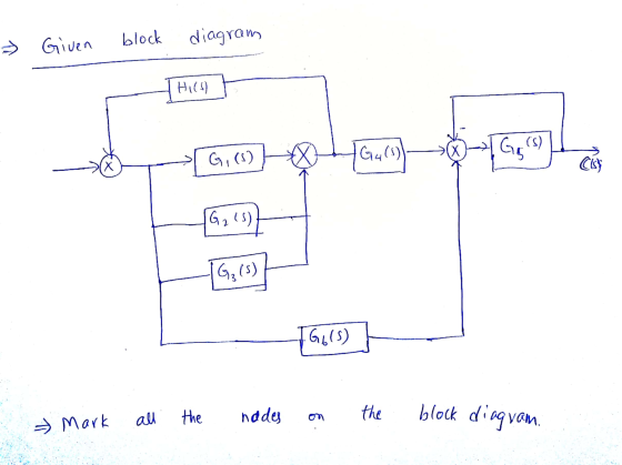
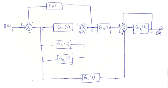
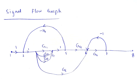
Use Mason's rule to find the transfer function of the signal-flow diagram shown in Figure below....
 Use Mason's rule to find the transfer function of the signal-flow diagram shown in Figure below. Knowing that: G1=7 G2=1/s G3=2 G4=1/s G5=-5 G6=1/s G7=-4 G8=5 G9=2 G10=9 G11=6 G12=3 H1=-4 H2=-2 H3=2 H4=-3 H5=-6 H6=1 G9 G10 G8 G11 R(s) G: G2 G3 G4 G5 G6 Y(s) 5 HI H2 H3 Ha Hs G12 HG
Find the closed-loop transfer function, T(s)-C(s)/R(s) for the following systems using block diagram reduction R(s)+ G1...
 Find the closed-loop transfer function, T(s)-C(s)/R(s) for the following systems using block diagram reduction R(s)+ G1 G2 G8 C(s) G2 G4 G7 G3 G1 G2 G3 G4. C(s) R(s)+ G5 G6 G7
3. There is a block diagram as shown in Fig. G1 G2 G3 Fig. 2 (a)...
 3. There is a block diagram as shown in Fig. G1 G2 G3 Fig. 2 (a) Convert the block diagram to a signal flow (b) Obtain its transfer function (G(s)-C(s)/R(s)) (c) As G -K.G3 G3 and its inputrt) is unit step, obtain the 50 condition of the P-controller(G1) for c(t) not to oscillate.
Q4. (a) Reduce the block diagram shown in Figure Q4a to a single mathematical expression suitable for implementation in MATLAB. Each letter represents a transfer function in the s-domain. (...
 Q4. (a) Reduce the block diagram shown in Figure Q4a to a single mathematical expression suitable for implementation in MATLAB. Each letter represents a transfer function in the s-domain. (10) G1 G2 G3 G4 G5 G6 Figure Q4a (b) Describe the process of generating the Nyquist plot. (c) Discuss how you would investigate the stability of a control system using the Nyquist plot and gain and phase margins of stability. (7) Q4 Total Marks [25] educe the block diagram shown...
6 Question: For the block diagram given in the following figure, the Control ratio is: *...
 6 Question: For the block diagram given in the following figure, the Control ratio is: * (3 Points) R(s) Y(s) G1 G2 G3 G1 (s) = K, G2 (s) = 1, G3 (s) = 21 S+6'
Find the transfer function Y(s)/R(s) in the given SFG. Use fx to input your answer. H2...
 Find the transfer function Y(s)/R(s) in the given SFG. Use fx to input your answer. H2 Н. L L2 G2 G3 G4 R(S) Gs GS G6 G7 Y(S) L3 L4 Ho H7 Using SFG, find the transfer function C(s)/R(s). Use fx to input your answer here. R(S) C(s) X x G1 H1 H2 Find the transfer function C/R for the given SFG. Use fx to input your answer. G1 X1 G2 X2 R С -H Reduce into a single transfer...
3-21. The block diagram of a control system is shown in Fig. 3P-21. (a) Draw an...
 3-21. The block diagram of a control system is shown in Fig. 3P-21. (a) Draw an equivalent SFG for the system. (b) Find the following transfer functions by applying the gain formula of the SFG directly to the block diagram. Y(s) Y(s) E(s) E(s) R(s)[N=0 N(s)R=0 R(s) N= N(s) R-0 (c) Compare the answers by applying the gain formula to the equivalent SFG. N() G (s) E(s) YS G () G3(s) H () Figure 3P-21
The figure below shows a block diagram of a feedback system. Both cascade clutch and forward...
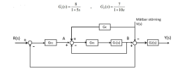 The figure below shows a block diagram of a feedback system.
Both cascade clutch and forward clutch are used to obtain the best
possible control. G1 and G2 have the following transfer functions:
G1(s) = 8 / 1+5s , G2(s)= 7/ 1+10s
a) Suppose that a (t) = σ (t) or A (s) = 1 / s. Dimension Gr1 =
K so that the residual error s e in the inner loop from A (s) to B
(s) becomes less...
The figure below shows a block diagram of a feedback system.
Both cascade clutch and forward clutch are used to obtain the best
possible control. G1 and G2 have the following transfer functions:
G1(s) = 8 / 1+5s , G2(s)= 7/ 1+10s
a) Suppose that a (t) = σ (t) or A (s) = 1 / s. Dimension Gr1 =
K so that the residual error s e in the inner loop from A (s) to B
(s) becomes less...
3) The single-line diagram of a three-phase power system is shown in Fig. 1. Equipment ratings...
 3) The single-line diagram of a three-phase power system is shown in Fig. 1. Equipment ratings are given as follows: G1 1,000 MVA, 15.0 kV, 20.18, o 0.07 pu G2 : 1,000 MVA. 15.0 kV, 攻=エ1 =エ2 = 0.20, ro = 0.10 pu G3 : 500 MVA, 13.8 kV. 1" = 띠 z2 = 0.15, zo 0.05 pu G4 : 750 MVA, 13.8 kV. ェd =ェ1 = 0.30, T2 = 0.40 ro = 0.10 pu Ti : 1,000 MVA. 15.0Δ/765Y...
QUESTION 1 (25 MARKS) a. A block diagram of a small private radio station is shown...
 QUESTION 1 (25 MARKS) a. A block diagram of a small private radio station is shown in Figure Q1(a). Operating at a frequency of 550 kHz, the station receives a full AM signal with 260 mW of power. The minimum and maximum bandwidths required by the system are 100 kHz and 200 kHz. If the surrounding temperature of the system is 18 °C, calculate the following: i. Noise Figure, NF for the system. (CO2: PO2 - 2.5 marks) ii. Noise...
 Use Mason's rule to find the transfer function of the signal-flow diagram shown in Figure below. Knowing that: G1=7 G2=1/s G3=2 G4=1/s G5=-5 G6=1/s G7=-4 G8=5 G9=2 G10=9 G11=6 G12=3 H1=-4 H2=-2 H3=2 H4=-3 H5=-6 H6=1 G9 G10 G8 G11 R(s) G: G2 G3 G4 G5 G6 Y(s) 5 HI H2 H3 Ha Hs G12 HG
 Find the closed-loop transfer function, T(s)-C(s)/R(s) for the following systems using block diagram reduction R(s)+ G1 G2 G8 C(s) G2 G4 G7 G3 G1 G2 G3 G4. C(s) R(s)+ G5 G6 G7
 3. There is a block diagram as shown in Fig. G1 G2 G3 Fig. 2 (a) Convert the block diagram to a signal flow (b) Obtain its transfer function (G(s)-C(s)/R(s)) (c) As G -K.G3 G3 and its inputrt) is unit step, obtain the 50 condition of the P-controller(G1) for c(t) not to oscillate.
 Q4. (a) Reduce the block diagram shown in Figure Q4a to a single mathematical expression suitable for implementation in MATLAB. Each letter represents a transfer function in the s-domain. (10) G1 G2 G3 G4 G5 G6 Figure Q4a (b) Describe the process of generating the Nyquist plot. (c) Discuss how you would investigate the stability of a control system using the Nyquist plot and gain and phase margins of stability. (7) Q4 Total Marks [25] educe the block diagram shown...
 6 Question: For the block diagram given in the following figure, the Control ratio is: * (3 Points) R(s) Y(s) G1 G2 G3 G1 (s) = K, G2 (s) = 1, G3 (s) = 21 S+6'
 Find the transfer function Y(s)/R(s) in the given SFG. Use fx to input your answer. H2 Н. L L2 G2 G3 G4 R(S) Gs GS G6 G7 Y(S) L3 L4 Ho H7 Using SFG, find the transfer function C(s)/R(s). Use fx to input your answer here. R(S) C(s) X x G1 H1 H2 Find the transfer function C/R for the given SFG. Use fx to input your answer. G1 X1 G2 X2 R С -H Reduce into a single transfer...
 3-21. The block diagram of a control system is shown in Fig. 3P-21. (a) Draw an equivalent SFG for the system. (b) Find the following transfer functions by applying the gain formula of the SFG directly to the block diagram. Y(s) Y(s) E(s) E(s) R(s)[N=0 N(s)R=0 R(s) N= N(s) R-0 (c) Compare the answers by applying the gain formula to the equivalent SFG. N() G (s) E(s) YS G () G3(s) H () Figure 3P-21
 The figure below shows a block diagram of a feedback system.
Both cascade clutch and forward clutch are used to obtain the best
possible control. G1 and G2 have the following transfer functions:
G1(s) = 8 / 1+5s , G2(s)= 7/ 1+10s
a) Suppose that a (t) = σ (t) or A (s) = 1 / s. Dimension Gr1 =
K so that the residual error s e in the inner loop from A (s) to B
(s) becomes less...
The figure below shows a block diagram of a feedback system.
Both cascade clutch and forward clutch are used to obtain the best
possible control. G1 and G2 have the following transfer functions:
G1(s) = 8 / 1+5s , G2(s)= 7/ 1+10s
a) Suppose that a (t) = σ (t) or A (s) = 1 / s. Dimension Gr1 =
K so that the residual error s e in the inner loop from A (s) to B
(s) becomes less...
 3) The single-line diagram of a three-phase power system is shown in Fig. 1. Equipment ratings are given as follows: G1 1,000 MVA, 15.0 kV, 20.18, o 0.07 pu G2 : 1,000 MVA. 15.0 kV, 攻=エ1 =エ2 = 0.20, ro = 0.10 pu G3 : 500 MVA, 13.8 kV. 1" = 띠 z2 = 0.15, zo 0.05 pu G4 : 750 MVA, 13.8 kV. ェd =ェ1 = 0.30, T2 = 0.40 ro = 0.10 pu Ti : 1,000 MVA. 15.0Δ/765Y...
 QUESTION 1 (25 MARKS) a. A block diagram of a small private radio station is shown in Figure Q1(a). Operating at a frequency of 550 kHz, the station receives a full AM signal with 260 mW of power. The minimum and maximum bandwidths required by the system are 100 kHz and 200 kHz. If the surrounding temperature of the system is 18 °C, calculate the following: i. Noise Figure, NF for the system. (CO2: PO2 - 2.5 marks) ii. Noise...
Most questions answered within 3 hours.
-
Where is the error in this code sequence?
String s1 = "Hello";
String s2 = "ello";...
asked 11 months ago -
Financial data for Joel de Paris, Inc., for last year
follow:
Joel de Paris, Inc.
Balance...
asked 11 months ago -
Consider this reaction:
Al2(SO4)3 (aq)+ BaCl3
(aq) Al2Cl6 (aq)- +
3BaSO4(s) . What is the...
asked 11 months ago -
Suppose that Savneet is considering increasing her
recent random sample from 20 car rentals to 40...
asked 11 months ago -
Trucks arrive at an unloading terminal at an average rate of 120
per hour.
Trucks arrive...
asked 11 months ago -
Why are methanol and ethanol completely soluble in water while
octanol is not very little soluble....
asked 11 months ago -
A facilities manager at a university reads in a research report
that the mean amount of...
asked 11 months ago -
When the CuSO4 is rehydrated by adding water to the anhydrous
compound, is this an endothermic...
asked 11 months ago -
A ray of sunlight is passing from diamond into crown glass; the
angle of incidence is...
asked 11 months ago -
A block of mass 0.249 kg is placed on top of a light, vertical
spring of...
asked 11 months ago -
how do the kidneys compensate in the presences of acidosis
a) trigger hyperventilate
b) reserve acid...
asked 11 months ago -
Question 501 pts
The rental rate of capital to the firm increases. Which of the
following...
asked 11 months ago