
Homework Answers

Add Answer to:
R S2 Sy R: с 6. A capacitor, three batteries, three resistors, and three switches (S1,...
A circuit is wired up as shown below. The capacitor is initially uncharged and switches S1 and S2 are initially open.
 A circuit is wired up as shown below. The capacitor is initially uncharged and switches S1 and S2 are initially open.1) What is the voltage across the capacitor immediately after
switch S1 is closed?Vc = 0Vc = VVc = 2V/32) What is the voltage across the capacitor after switch S1 has
been closed for a very long time?Vc = 0Vc = VVc = 2V/33) After being closed a long time, switch 1 is opened and switch
2 is closed. What...
A circuit is wired up as shown below. The capacitor is initially uncharged and switches S1 and S2 are initially open.1) What is the voltage across the capacitor immediately after
switch S1 is closed?Vc = 0Vc = VVc = 2V/32) What is the voltage across the capacitor after switch S1 has
been closed for a very long time?Vc = 0Vc = VVc = 2V/33) After being closed a long time, switch 1 is opened and switch
2 is closed. What...
The figure shows a circuit cantaining three switches, labeled S1, S2, and S3. Find the current...
 The figure shows a circuit cantaining three
switches, labeled S1, S2, and S3. Find the current at "a" for all
possible combinations of switch settings. Put ? = 70
V, R1 = 25 ?, and R2 = 9 ?.
Assume that the battery has no resistance.
Current at "a" for S2 and S3 closed and S1
open?
Current at "a" for S2 closed and S1 and S3
open?
The figure shows a circuit cantaining three
switches, labeled S1, S2, and S3. Find the current at "a" for all
possible combinations of switch settings. Put ? = 70
V, R1 = 25 ?, and R2 = 9 ?.
Assume that the battery has no resistance.
Current at "a" for S2 and S3 closed and S1
open?
Current at "a" for S2 closed and S1 and S3
open?
The figure shows a circuit containing three switches, labeled S1, S2, and S3. Find the current...
 The figure shows a circuit containing three switches, labeled
S1, S2, and S3. Find the current at "a" for all possible
combinations of switch settings. Put e = 90 V, R1 = 20 Ohm, and R2
= 10 Ohm. Assume that the battery has no resistance.
a. Current at "a" for S1 and S3 closed, S2 open (in A)
b. Current at "a" for S1 and S2 closed and S3 open (in A)
c. Current at "a" for SI and...
The figure shows a circuit containing three switches, labeled
S1, S2, and S3. Find the current at "a" for all possible
combinations of switch settings. Put e = 90 V, R1 = 20 Ohm, and R2
= 10 Ohm. Assume that the battery has no resistance.
a. Current at "a" for S1 and S3 closed, S2 open (in A)
b. Current at "a" for S1 and S2 closed and S3 open (in A)
c. Current at "a" for SI and...
The circuit of the figure shows a capacitor, two ideal batteries, two resistors, and a switch...
 The
circuit of the figure shows a capacitor, two ideal batteries, two
resistors, and a switch S. Initially S has been open for a long
time. If it is then closed for a long time, what is the change in
the charge on the capacitor? Assume C = 43 μF, 1 = 1.7 V, 2 = 6.0
V, R1 = 0.41 Ω, and R2 = 0.59 Ω.
The
circuit of the figure shows a capacitor, two ideal batteries, two
resistors, and a switch S. Initially S has been open for a long
time. If it is then closed for a long time, what is the change in
the charge on the capacitor? Assume C = 43 μF, 1 = 1.7 V, 2 = 6.0
V, R1 = 0.41 Ω, and R2 = 0.59 Ω.
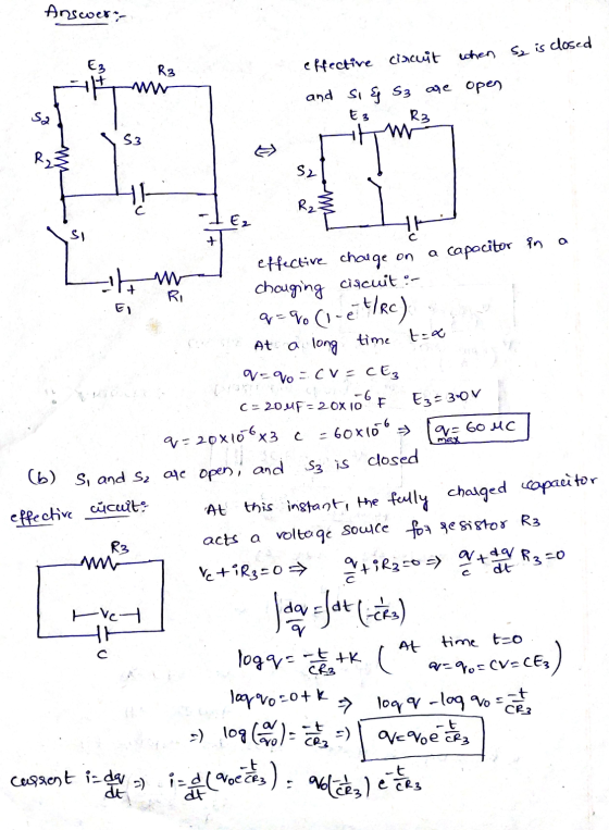
5. The circuit below has two capacitors, three resistors, a battery and two switches. The switches,...
 5. The circuit below has two capacitors, three resistors, a battery and two switches. The switches, S1 and S2, have been open for a long time and the capacitors are uncharged. At time t O both switches arc closed. 1MuF = 10^-6 F. a. Immediately after both switches are closed, what is the current I2? b. After the switches have been closed for a very long time, what is the current I1? c. After the switches have been closed for...
2) Shown below is a c R2 = 7 Ω, R3 = 24 Ω, R4 = 10 ircuit with two switches. Si and S2M = 15 V, V...
 2) Shown below is a c R2 = 7 Ω, R3 = 24 Ω, R4 = 10 ircuit with two switches. Si and S2M = 15 V, V.-5 V, V,-20 V, Rı = 15 Ω . 25s2 C,200F v -,,I -R, Г 2:0 start atp sition A. This creates two dependent circuits. The left circuit with only resistors '5 V-15A)(T)-YAG).2ov-ocharges the capacitor C, through resistor Rs with battery Vs(the capacitor is initially The switch 1 will start in the on/closed...
The figure below shows three resistors (Ri-15.5 ฉ circuit. R,. '80 , and R,. ii 50)...
 The figure below shows three resistors (Ri-15.5 ฉ circuit. R,. '80 , and R,. ii 50) and two batteries connected in a 40.0 V Ri 22.0 V AR (a) What is the current in each of the resistors? I3 (b) How much power is delivered to each of the resistors? P1
Two batteries, a capacitor, and two light bulbs are connected by wires. The batteries have a...
 Two batteries, a capacitor, and two light bulbs are connected by
wires. The batteries have a potential difference emf, the capacitor
has capacitance C, and the bulbs have resistance R. Initially the
capacitor is uncharged and the switch has been closed.
A)Write down the three loop rules and the node rule for this
circuit and label the currents on the picture.
B) Find the initial currents running through each bulb.
C)What is the current running through each bulb a long...
Two batteries, a capacitor, and two light bulbs are connected by
wires. The batteries have a potential difference emf, the capacitor
has capacitance C, and the bulbs have resistance R. Initially the
capacitor is uncharged and the switch has been closed.
A)Write down the three loop rules and the node rule for this
circuit and label the currents on the picture.
B) Find the initial currents running through each bulb.
C)What is the current running through each bulb a long...
step by step solution A circuit consisting of three ideal batteries with voltages &I. 82, and...
 step by step solution
A circuit consisting of three ideal batteries with voltages &I. 82, and 83, and three ideal resistors with resistances R R2, and Rs, is shown in the figure. Calculate the current Ip through point P. Let the sign of the current correspond to its direction, with "up" being positive. R, 81 = 29,5 v, 82 = 10.5 V, 83-31.5 V Ri 2.70 ks2, R2 17.5 k2, R 7.00 k2 mA
step by step solution
A circuit consisting of three ideal batteries with voltages &I. 82, and 83, and three ideal resistors with resistances R R2, and Rs, is shown in the figure. Calculate the current Ip through point P. Let the sign of the current correspond to its direction, with "up" being positive. R, 81 = 29,5 v, 82 = 10.5 V, 83-31.5 V Ri 2.70 ks2, R2 17.5 k2, R 7.00 k2 mA
The circuit shown in the figure below contains three resistors (R1, R2, and R3) and three...
 The circuit shown in the figure below contains three resistors (R1, R2, and R3) and three batteries (VA, Vg, and Vc). The resistor values are: R7-2 Ohms, R-R3-4 Ohms, and the battery voltages are VA=25 V. V8-15 V, and Vc=20 V. When the circuit is connected, what will be the power dissipated by Rg? Vc R, VA VE R₂ R3 1.25 W 0 2.0 W 5.0 W O 6.25 W O 8.13 W The circuit shown in the figure contains...
 A circuit is wired up as shown below. The capacitor is initially uncharged and switches S1 and S2 are initially open.1) What is the voltage across the capacitor immediately after
switch S1 is closed?Vc = 0Vc = VVc = 2V/32) What is the voltage across the capacitor after switch S1 has
been closed for a very long time?Vc = 0Vc = VVc = 2V/33) After being closed a long time, switch 1 is opened and switch
2 is closed. What...
A circuit is wired up as shown below. The capacitor is initially uncharged and switches S1 and S2 are initially open.1) What is the voltage across the capacitor immediately after
switch S1 is closed?Vc = 0Vc = VVc = 2V/32) What is the voltage across the capacitor after switch S1 has
been closed for a very long time?Vc = 0Vc = VVc = 2V/33) After being closed a long time, switch 1 is opened and switch
2 is closed. What...
 The figure shows a circuit cantaining three
switches, labeled S1, S2, and S3. Find the current at "a" for all
possible combinations of switch settings. Put ? = 70
V, R1 = 25 ?, and R2 = 9 ?.
Assume that the battery has no resistance.
Current at "a" for S2 and S3 closed and S1
open?
Current at "a" for S2 closed and S1 and S3
open?
The figure shows a circuit cantaining three
switches, labeled S1, S2, and S3. Find the current at "a" for all
possible combinations of switch settings. Put ? = 70
V, R1 = 25 ?, and R2 = 9 ?.
Assume that the battery has no resistance.
Current at "a" for S2 and S3 closed and S1
open?
Current at "a" for S2 closed and S1 and S3
open?
 The figure shows a circuit containing three switches, labeled
S1, S2, and S3. Find the current at "a" for all possible
combinations of switch settings. Put e = 90 V, R1 = 20 Ohm, and R2
= 10 Ohm. Assume that the battery has no resistance.
a. Current at "a" for S1 and S3 closed, S2 open (in A)
b. Current at "a" for S1 and S2 closed and S3 open (in A)
c. Current at "a" for SI and...
The figure shows a circuit containing three switches, labeled
S1, S2, and S3. Find the current at "a" for all possible
combinations of switch settings. Put e = 90 V, R1 = 20 Ohm, and R2
= 10 Ohm. Assume that the battery has no resistance.
a. Current at "a" for S1 and S3 closed, S2 open (in A)
b. Current at "a" for S1 and S2 closed and S3 open (in A)
c. Current at "a" for SI and...
 The
circuit of the figure shows a capacitor, two ideal batteries, two
resistors, and a switch S. Initially S has been open for a long
time. If it is then closed for a long time, what is the change in
the charge on the capacitor? Assume C = 43 μF, 1 = 1.7 V, 2 = 6.0
V, R1 = 0.41 Ω, and R2 = 0.59 Ω.
The
circuit of the figure shows a capacitor, two ideal batteries, two
resistors, and a switch S. Initially S has been open for a long
time. If it is then closed for a long time, what is the change in
the charge on the capacitor? Assume C = 43 μF, 1 = 1.7 V, 2 = 6.0
V, R1 = 0.41 Ω, and R2 = 0.59 Ω.
 5. The circuit below has two capacitors, three resistors, a battery and two switches. The switches, S1 and S2, have been open for a long time and the capacitors are uncharged. At time t O both switches arc closed. 1MuF = 10^-6 F. a. Immediately after both switches are closed, what is the current I2? b. After the switches have been closed for a very long time, what is the current I1? c. After the switches have been closed for...
 2) Shown below is a c R2 = 7 Ω, R3 = 24 Ω, R4 = 10 ircuit with two switches. Si and S2M = 15 V, V.-5 V, V,-20 V, Rı = 15 Ω . 25s2 C,200F v -,,I -R, Г 2:0 start atp sition A. This creates two dependent circuits. The left circuit with only resistors '5 V-15A)(T)-YAG).2ov-ocharges the capacitor C, through resistor Rs with battery Vs(the capacitor is initially The switch 1 will start in the on/closed...
 The figure below shows three resistors (Ri-15.5 ฉ circuit. R,. '80 , and R,. ii 50) and two batteries connected in a 40.0 V Ri 22.0 V AR (a) What is the current in each of the resistors? I3 (b) How much power is delivered to each of the resistors? P1
 Two batteries, a capacitor, and two light bulbs are connected by
wires. The batteries have a potential difference emf, the capacitor
has capacitance C, and the bulbs have resistance R. Initially the
capacitor is uncharged and the switch has been closed.
A)Write down the three loop rules and the node rule for this
circuit and label the currents on the picture.
B) Find the initial currents running through each bulb.
C)What is the current running through each bulb a long...
Two batteries, a capacitor, and two light bulbs are connected by
wires. The batteries have a potential difference emf, the capacitor
has capacitance C, and the bulbs have resistance R. Initially the
capacitor is uncharged and the switch has been closed.
A)Write down the three loop rules and the node rule for this
circuit and label the currents on the picture.
B) Find the initial currents running through each bulb.
C)What is the current running through each bulb a long...
 step by step solution
A circuit consisting of three ideal batteries with voltages &I. 82, and 83, and three ideal resistors with resistances R R2, and Rs, is shown in the figure. Calculate the current Ip through point P. Let the sign of the current correspond to its direction, with "up" being positive. R, 81 = 29,5 v, 82 = 10.5 V, 83-31.5 V Ri 2.70 ks2, R2 17.5 k2, R 7.00 k2 mA
step by step solution
A circuit consisting of three ideal batteries with voltages &I. 82, and 83, and three ideal resistors with resistances R R2, and Rs, is shown in the figure. Calculate the current Ip through point P. Let the sign of the current correspond to its direction, with "up" being positive. R, 81 = 29,5 v, 82 = 10.5 V, 83-31.5 V Ri 2.70 ks2, R2 17.5 k2, R 7.00 k2 mA
 The circuit shown in the figure below contains three resistors (R1, R2, and R3) and three batteries (VA, Vg, and Vc). The resistor values are: R7-2 Ohms, R-R3-4 Ohms, and the battery voltages are VA=25 V. V8-15 V, and Vc=20 V. When the circuit is connected, what will be the power dissipated by Rg? Vc R, VA VE R₂ R3 1.25 W 0 2.0 W 5.0 W O 6.25 W O 8.13 W The circuit shown in the figure contains...
Most questions answered within 3 hours.
-
Where is the error in this code sequence?
String s1 = "Hello";
String s2 = "ello";...
asked 10 months ago -
Financial data for Joel de Paris, Inc., for last year
follow:
Joel de Paris, Inc.
Balance...
asked 10 months ago -
Consider this reaction:
Al2(SO4)3 (aq)+ BaCl3
(aq) Al2Cl6 (aq)- +
3BaSO4(s) . What is the...
asked 10 months ago -
Suppose that Savneet is considering increasing her
recent random sample from 20 car rentals to 40...
asked 10 months ago -
Trucks arrive at an unloading terminal at an average rate of 120
per hour.
Trucks arrive...
asked 10 months ago -
Why are methanol and ethanol completely soluble in water while
octanol is not very little soluble....
asked 10 months ago -
A facilities manager at a university reads in a research report
that the mean amount of...
asked 10 months ago -
When the CuSO4 is rehydrated by adding water to the anhydrous
compound, is this an endothermic...
asked 10 months ago -
A ray of sunlight is passing from diamond into crown glass; the
angle of incidence is...
asked 10 months ago -
A block of mass 0.249 kg is placed on top of a light, vertical
spring of...
asked 10 months ago -
how do the kidneys compensate in the presences of acidosis
a) trigger hyperventilate
b) reserve acid...
asked 10 months ago -
Question 501 pts
The rental rate of capital to the firm increases. Which of the
following...
asked 10 months ago