
Homework Answers
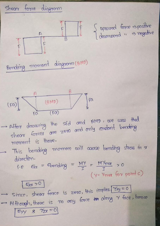
In this problem we need to give the sign of the stresses at point c.I assumed the A and B as support point and C as mid point .
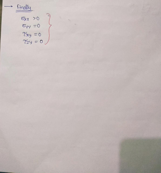
I shown all the calculation and reason for the answer.Here,note that the stress in x direction is the bending stress and it is positive since it causes tension in the upper most fiber.We can see the deformed shape of the beam.
Hope it will help you to understand the concept.

Add Answer to:
The beam is simply supported by two pin joints, each located a distance afrom each end...
For a beam of rectangular cross section, height b, depth d, is simply supported (by pin...
 For a beam of rectangular cross section, height b, depth d, is simply supported (by pin joints at each end) over a span of length L and carries a point load W at mid span. Determine the distribution and maximum value of the normal stress.
03. (25%) Stress and deflection, of simply supported beam 6.08 inches from the bottom flange edge...
 03. (25%) Stress and deflection, of simply supported beam 6.08 inches from the bottom flange edge y supported beam consists of a steel shape shown below where the neutral axis is located 2 in. 10 in. 14 in 2 in. 2 in. 1Y Determine the FBD and reactions. The left support is a pin and the right supports a roller. b) Determine the maximum bending moment and it's location (intuition if explained is ok) c) Determine the moment of inertia,...
Consider the two-beam system below. The beams are pin jointed at B and simply supported at...
 Consider the two-beam system below. The beams are pin jointed at B and simply supported at their other ends at the base of the system). A spring of stiffness, k, connects the two beams to prevent the system collapsing. The unloaded length of the spring is h/2. A load of magnitude Pis applied at point B. } a. Using the method of virtual work, find the value of that keeps the system in equilibrium with the given geometry shown in...
A rigid beam ABCD is supported by a pin at B and two cables located at...
 A rigid beam ABCD is supported by a pin at B and two cables located at A and C. The cables have a 30 mm diameter and are made of steel with yield strength of 800 MPa and elastic modulus of 200 GPa. The beam is designed to resist a vertical load P applied at D equal to 200 kN. a) Find the forces developed in each cable b) Find the corresponding vertical displacement at point where the load is...
The steel beam ABCD shown in the figure is simply supported at Cand supported at Band...
 The steel beam ABCD shown in the figure is simply supported at Cand supported at Band D by shoulder steel bolts, each having a diameter of 10 mm. The lengths of BE and DF are 50 mm and 60 mm, respectively. The beam has a second area moment of 21 x 103 mm4. Prior to loading, the members are stress free. A force of P= 2000 N is then applied at point A. Using procedure 2 of Sec. 4– 10,...
L uestion from this section) Question 5 A simply supported beam has a span of 6...
 L uestion from this section) Question 5 A simply supported beam has a span of 6 m and supports a concentrated load P 108 kN, as shown in Figure Q5. The beam has a rectangular cross section that is 0.2 m wide and 0.6 m high. Points A, B and C are located at a cross section 0.9 m away from the left support of the beam. Point A is located at the top of the beam, C is at...
A simply supported 2 x 4 beam spans 10 feet. It is designed to handle two...
 A simply supported 2 x 4 beam spans 10 feet. It is designed to handle two equal concentrated loads of 200 lbs. The loads occur at 30" from each end. The beam is made of Douglas Fir (Young's Modulus 1.95 x 10⁵ PSI). Assume that the beam is oriented in the proper direction to minimize stress. Don't forget to use actual dimensions instead of nominal dimensions. 2. a. b. c. d. e. Calculate the maximum shear force. Calculate the maximum...
The beam shown (Figure 1) is supported by a pin at A and a cable at...
 The beam shown (Figure 1) is
supported by a pin at A and a cable at B. Two
loads P = 13 kN are applied straight down from the
centerline of the bottom face. Determine the state of stress at the
point shown (Figure 2) in a section 2 m from the wall. The
dimensions are w = 5.2 cm , h = 10.5 cm ,
L = 0.8 m , a = 1.5 cm , and b = 4...
The beam shown (Figure 1) is
supported by a pin at A and a cable at B. Two
loads P = 13 kN are applied straight down from the
centerline of the bottom face. Determine the state of stress at the
point shown (Figure 2) in a section 2 m from the wall. The
dimensions are w = 5.2 cm , h = 10.5 cm ,
L = 0.8 m , a = 1.5 cm , and b = 4...
The beam shown (Figure 1) is supported by a pin at A and a cable at...
 The beam shown (Figure 1) is supported by a pin at A
and a cable at B. Two loads P = 13 kN are applied
straight down from the centerline of the bottom face. Determine the
state of stress at the point shown (Figure 2) in a section 2 m from
the wall. The dimensions are w = 5.2 cm , h =
10.5 cm , L = 0.8 m , a = 1.5 cm , and b
= 4...
The beam shown (Figure 1) is supported by a pin at A
and a cable at B. Two loads P = 13 kN are applied
straight down from the centerline of the bottom face. Determine the
state of stress at the point shown (Figure 2) in a section 2 m from
the wall. The dimensions are w = 5.2 cm , h =
10.5 cm , L = 0.8 m , a = 1.5 cm , and b
= 4...
The beam shown (Figure 1) is supported by a pin at A and a cable at...
 The beam shown (Figure 1) is supported by a pin at A and a cable at
B. Two loads P = 13 kN are applied straight down
from the centerline of the bottom face. Determine the state of
stress at the point shown (Figure 2) in a section 2 m from the
wall. The dimensions are w = 5.2 cm , h = 10.5 cm
, L = 0.8 m , a = 1.5 cm , and b = 4...
The beam shown (Figure 1) is supported by a pin at A and a cable at
B. Two loads P = 13 kN are applied straight down
from the centerline of the bottom face. Determine the state of
stress at the point shown (Figure 2) in a section 2 m from the
wall. The dimensions are w = 5.2 cm , h = 10.5 cm
, L = 0.8 m , a = 1.5 cm , and b = 4...
 For a beam of rectangular cross section, height b, depth d, is simply supported (by pin joints at each end) over a span of length L and carries a point load W at mid span. Determine the distribution and maximum value of the normal stress.
 03. (25%) Stress and deflection, of simply supported beam 6.08 inches from the bottom flange edge y supported beam consists of a steel shape shown below where the neutral axis is located 2 in. 10 in. 14 in 2 in. 2 in. 1Y Determine the FBD and reactions. The left support is a pin and the right supports a roller. b) Determine the maximum bending moment and it's location (intuition if explained is ok) c) Determine the moment of inertia,...
 Consider the two-beam system below. The beams are pin jointed at B and simply supported at their other ends at the base of the system). A spring of stiffness, k, connects the two beams to prevent the system collapsing. The unloaded length of the spring is h/2. A load of magnitude Pis applied at point B. } a. Using the method of virtual work, find the value of that keeps the system in equilibrium with the given geometry shown in...
 A rigid beam ABCD is supported by a pin at B and two cables located at A and C. The cables have a 30 mm diameter and are made of steel with yield strength of 800 MPa and elastic modulus of 200 GPa. The beam is designed to resist a vertical load P applied at D equal to 200 kN. a) Find the forces developed in each cable b) Find the corresponding vertical displacement at point where the load is...
 The steel beam ABCD shown in the figure is simply supported at Cand supported at Band D by shoulder steel bolts, each having a diameter of 10 mm. The lengths of BE and DF are 50 mm and 60 mm, respectively. The beam has a second area moment of 21 x 103 mm4. Prior to loading, the members are stress free. A force of P= 2000 N is then applied at point A. Using procedure 2 of Sec. 4– 10,...
 L uestion from this section) Question 5 A simply supported beam has a span of 6 m and supports a concentrated load P 108 kN, as shown in Figure Q5. The beam has a rectangular cross section that is 0.2 m wide and 0.6 m high. Points A, B and C are located at a cross section 0.9 m away from the left support of the beam. Point A is located at the top of the beam, C is at...
 A simply supported 2 x 4 beam spans 10 feet. It is designed to handle two equal concentrated loads of 200 lbs. The loads occur at 30" from each end. The beam is made of Douglas Fir (Young's Modulus 1.95 x 10⁵ PSI). Assume that the beam is oriented in the proper direction to minimize stress. Don't forget to use actual dimensions instead of nominal dimensions. 2. a. b. c. d. e. Calculate the maximum shear force. Calculate the maximum...
 The beam shown (Figure 1) is
supported by a pin at A and a cable at B. Two
loads P = 13 kN are applied straight down from the
centerline of the bottom face. Determine the state of stress at the
point shown (Figure 2) in a section 2 m from the wall. The
dimensions are w = 5.2 cm , h = 10.5 cm ,
L = 0.8 m , a = 1.5 cm , and b = 4...
The beam shown (Figure 1) is
supported by a pin at A and a cable at B. Two
loads P = 13 kN are applied straight down from the
centerline of the bottom face. Determine the state of stress at the
point shown (Figure 2) in a section 2 m from the wall. The
dimensions are w = 5.2 cm , h = 10.5 cm ,
L = 0.8 m , a = 1.5 cm , and b = 4...
 The beam shown (Figure 1) is supported by a pin at A
and a cable at B. Two loads P = 13 kN are applied
straight down from the centerline of the bottom face. Determine the
state of stress at the point shown (Figure 2) in a section 2 m from
the wall. The dimensions are w = 5.2 cm , h =
10.5 cm , L = 0.8 m , a = 1.5 cm , and b
= 4...
The beam shown (Figure 1) is supported by a pin at A
and a cable at B. Two loads P = 13 kN are applied
straight down from the centerline of the bottom face. Determine the
state of stress at the point shown (Figure 2) in a section 2 m from
the wall. The dimensions are w = 5.2 cm , h =
10.5 cm , L = 0.8 m , a = 1.5 cm , and b
= 4...
 The beam shown (Figure 1) is supported by a pin at A and a cable at
B. Two loads P = 13 kN are applied straight down
from the centerline of the bottom face. Determine the state of
stress at the point shown (Figure 2) in a section 2 m from the
wall. The dimensions are w = 5.2 cm , h = 10.5 cm
, L = 0.8 m , a = 1.5 cm , and b = 4...
The beam shown (Figure 1) is supported by a pin at A and a cable at
B. Two loads P = 13 kN are applied straight down
from the centerline of the bottom face. Determine the state of
stress at the point shown (Figure 2) in a section 2 m from the
wall. The dimensions are w = 5.2 cm , h = 10.5 cm
, L = 0.8 m , a = 1.5 cm , and b = 4...
Most questions answered within 3 hours.
-
Where is the error in this code sequence?
String s1 = "Hello";
String s2 = "ello";...
asked 10 months ago -
Financial data for Joel de Paris, Inc., for last year
follow:
Joel de Paris, Inc.
Balance...
asked 10 months ago -
Consider this reaction:
Al2(SO4)3 (aq)+ BaCl3
(aq) Al2Cl6 (aq)- +
3BaSO4(s) . What is the...
asked 10 months ago -
Suppose that Savneet is considering increasing her
recent random sample from 20 car rentals to 40...
asked 10 months ago -
Trucks arrive at an unloading terminal at an average rate of 120
per hour.
Trucks arrive...
asked 10 months ago -
Why are methanol and ethanol completely soluble in water while
octanol is not very little soluble....
asked 10 months ago -
A facilities manager at a university reads in a research report
that the mean amount of...
asked 10 months ago -
When the CuSO4 is rehydrated by adding water to the anhydrous
compound, is this an endothermic...
asked 10 months ago -
A ray of sunlight is passing from diamond into crown glass; the
angle of incidence is...
asked 10 months ago -
A block of mass 0.249 kg is placed on top of a light, vertical
spring of...
asked 10 months ago -
how do the kidneys compensate in the presences of acidosis
a) trigger hyperventilate
b) reserve acid...
asked 10 months ago -
Question 501 pts
The rental rate of capital to the firm increases. Which of the
following...
asked 10 months ago