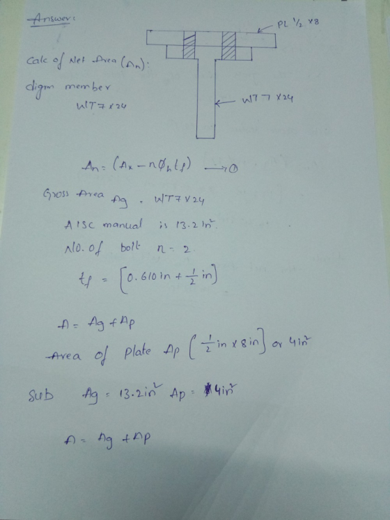
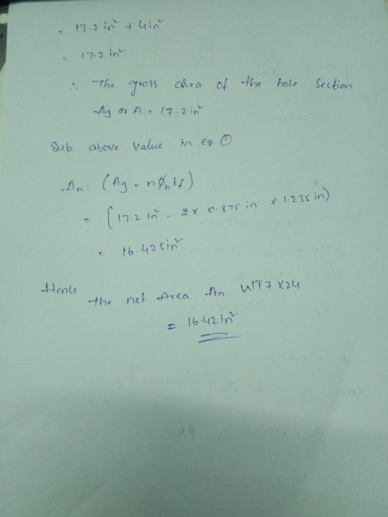
 compute the net area
Homework Answers
Add Answer to:
compute the net area
3-8 The built-up section shown in Fig. P3-8 for which ¾-in bolts...
FIGURE P3-19 aSection The brass bar shown in Fig. P3-20, which has a uniform cross-sectional area...
 FIGURE P3-19 aSection The brass bar shown in Fig. P3-20, which has a uniform cross-sectional area of 2 in.2, is subjected to the forces shown. Determine the total deformation of the bar. The modulus of elasticity of brass is E = 17 x 102 ksi. si 40 kips 30 kips 30 kips CI 2ft . (4ft -tl 3 ft FIGURE P3-20
Q2. Determine the effective net area of a channel section C15 x 50 (A36 steel) with two lines of 4-in bolts in its...
 Q2. Determine the effective net area of a channel section C15 x 50 (A36 steel) with two lines of 4-in bolts in its web (four in a line 4-in on center) as shown in Fig. Q2. The properties of the channel are as follows: A 14.7 in2, d 0.65 in, I 404 in, Iy 11.0 in, = 0.799 in. = 15.0 in, tw = 0.716 in, br = 3.72 in, t - (25%) ELEVATION $4 in 2 in 2 in...
S- Section FIGURE P3.2-3 APL⅜x6tension member is steel is A36. Assume that A, A, and compute...
 S- Section FIGURE P3.2-3 APL⅜x6tension member is steel is A36. Assume that A, A, and compute the following. a. The design strength for LRFD. b. The allowable strength for ASD. 32-4 APLx6 tension member is welded to a gusset plate as shown in Figure P3.2-4. The :and compute 3.2-4 ameter bolts, as shown A,A, and compute the FIGURE P3.2-4 ion member shown in Figure P3.2.5 is a PL tax 8 of A36 steel. The mem- ted to a gusset plate...
Problem 1: Compute the maximum service axial compression load permitted on the built-up cross-section of the...
 Problem 1: Compute the maximum service axial compression load permitted on the built-up cross-section of the accompanying figure. The load is 30% dead load and 70% live load. The steel used is A992, and the effective lengths are (KL), = 14 ft and (KL), = 42 ft. 3/8x 18 3/8 x 32 3/8 x 18
5. A built-up section consists of two MC18 x 42.27 identical channels placed back to back...
 5. A built-up section consists of two MC18 x 42.27 identical channels placed back to back and two plates PL % x 16 as shown in Fig. Q5. The section is subjected to axial loads P= 100 k and P check. Properties of each channel is as follows: A= 12.6 in2, d = 18.00 in, I,= 554 in*, I 14.3in, = 0.877 in. Use steel with F,= 50 ksi. 300 k. Is this section satisfactory for the given loads? Use...
need help asap Problems 97 3.8 22. Determine the effective net areas of the sections shown by using the U values giv...
 need help asap
Problems 97 3.8 22. Determine the effective net areas of the sections shown by using the U values given in Table 3.2 of this chapter. Assume three bolts in a line 3 L8 X 4 X 4 1 in bolts 4 in 4 in 4 in 6 in FIGURE P3-20 21. Determne the effective net area of the MC12 X 40 shown. Assume the holes are for 7/8 in bolts. (Ans. 9.02 in it
Problems 97 3.8...
need help asap
Problems 97 3.8 22. Determine the effective net areas of the sections shown by using the U values given in Table 3.2 of this chapter. Assume three bolts in a line 3 L8 X 4 X 4 1 in bolts 4 in 4 in 4 in 6 in FIGURE P3-20 21. Determne the effective net area of the MC12 X 40 shown. Assume the holes are for 7/8 in bolts. (Ans. 9.02 in it
Problems 97 3.8...
Question 8. Section 2-3 Shear Stresses 6. In the bolted connection of Fig. 2-8, assume that...
 Question 8.
Section 2-3 Shear Stresses 6. In the bolted connection of Fig. 2-8, assume that the bolts are , in. in diameter and that the allowable shear stress for the bolts is 14,500 psi. Based on bolt shear only, compute the safe allowable load P that may be applied 7. Compute the force required to punch a 1 in. diameter hole through a ½ in, thick boiler plate. The ultimate shear strength for the material is 42,000 psi. 8....
Question 8.
Section 2-3 Shear Stresses 6. In the bolted connection of Fig. 2-8, assume that the bolts are , in. in diameter and that the allowable shear stress for the bolts is 14,500 psi. Based on bolt shear only, compute the safe allowable load P that may be applied 7. Compute the force required to punch a 1 in. diameter hole through a ½ in, thick boiler plate. The ultimate shear strength for the material is 42,000 psi. 8....
1. The section of the sealed joint shown in Fig. Q.1 is loaded by P 6.0 kip. The members have E-16 Mps, All bolts have been carefully preloaded to F. 25 kip a. If hardened-steel washers (American...
 1. The section of the sealed joint shown in Fig. Q.1 is loaded by P 6.0 kip. The members have E-16 Mps, All bolts have been carefully preloaded to F. 25 kip a. If hardened-steel washers (American Standard, Narrow) are to be used under the head and nut, what length of bolts should be used (round up to the nearest 0.1 in)? (8 pts) b. Find kb, km (using 30° cone) and C. (24 pts) c Using the modifed Goodman...
our professor uses shigley's mechanical engineering design 9th edition The section of the sealed joint shown in Fig. Q.1 is loaded by P 6.0 kip. The members have E-16 Mpsi. All bolts have been...
 our professor uses shigley's mechanical engineering
design 9th edition
The section of the sealed joint shown in Fig. Q.1 is loaded by P 6.0 kip. The members have E-16 Mpsi. All bolts have been carefully preloaded to Fi 25 kip each. a. If hardened-steel washers (American Standard, Narrow) are to be used under the head and nut, what length of bolts should be used (round up to the nearest 0.1 in)? (8 pts) b. Find kb, Km (using 30° cone)...
our professor uses shigley's mechanical engineering
design 9th edition
The section of the sealed joint shown in Fig. Q.1 is loaded by P 6.0 kip. The members have E-16 Mpsi. All bolts have been carefully preloaded to Fi 25 kip each. a. If hardened-steel washers (American Standard, Narrow) are to be used under the head and nut, what length of bolts should be used (round up to the nearest 0.1 in)? (8 pts) b. Find kb, Km (using 30° cone)...
Problem No. 1: (25 points) Compute the capacity of the connection shown in Fig. 1 under tensile loading. The connection...
 Problem No. 1: (25 points) Compute the capacity of the connection shown in Fig. 1 under tensile loading. The connection is in between a C10x25 (channel section) and aL6x4x 3/4 angle with 3/4" @bolts at the longer side of the angle C10x25, A36 Steel L6 x4x 3/4, A36 Steel 1.5" 3" 3/4 ibolts 1.5 1.5 1.5" 1.5" C10x25, A36 Steel 1.5 3" 339 Fig.1 15:
Problem No. 1: (25 points) Compute the capacity of the connection shown in Fig. 1...
Problem No. 1: (25 points) Compute the capacity of the connection shown in Fig. 1 under tensile loading. The connection is in between a C10x25 (channel section) and aL6x4x 3/4 angle with 3/4" @bolts at the longer side of the angle C10x25, A36 Steel L6 x4x 3/4, A36 Steel 1.5" 3" 3/4 ibolts 1.5 1.5 1.5" 1.5" C10x25, A36 Steel 1.5 3" 339 Fig.1 15:
Problem No. 1: (25 points) Compute the capacity of the connection shown in Fig. 1...
 FIGURE P3-19 aSection The brass bar shown in Fig. P3-20, which has a uniform cross-sectional area of 2 in.2, is subjected to the forces shown. Determine the total deformation of the bar. The modulus of elasticity of brass is E = 17 x 102 ksi. si 40 kips 30 kips 30 kips CI 2ft . (4ft -tl 3 ft FIGURE P3-20
 Q2. Determine the effective net area of a channel section C15 x 50 (A36 steel) with two lines of 4-in bolts in its web (four in a line 4-in on center) as shown in Fig. Q2. The properties of the channel are as follows: A 14.7 in2, d 0.65 in, I 404 in, Iy 11.0 in, = 0.799 in. = 15.0 in, tw = 0.716 in, br = 3.72 in, t - (25%) ELEVATION $4 in 2 in 2 in...
 S- Section FIGURE P3.2-3 APL⅜x6tension member is steel is A36. Assume that A, A, and compute the following. a. The design strength for LRFD. b. The allowable strength for ASD. 32-4 APLx6 tension member is welded to a gusset plate as shown in Figure P3.2-4. The :and compute 3.2-4 ameter bolts, as shown A,A, and compute the FIGURE P3.2-4 ion member shown in Figure P3.2.5 is a PL tax 8 of A36 steel. The mem- ted to a gusset plate...
 Problem 1: Compute the maximum service axial compression load permitted on the built-up cross-section of the accompanying figure. The load is 30% dead load and 70% live load. The steel used is A992, and the effective lengths are (KL), = 14 ft and (KL), = 42 ft. 3/8x 18 3/8 x 32 3/8 x 18
 5. A built-up section consists of two MC18 x 42.27 identical channels placed back to back and two plates PL % x 16 as shown in Fig. Q5. The section is subjected to axial loads P= 100 k and P check. Properties of each channel is as follows: A= 12.6 in2, d = 18.00 in, I,= 554 in*, I 14.3in, = 0.877 in. Use steel with F,= 50 ksi. 300 k. Is this section satisfactory for the given loads? Use...
 need help asap
Problems 97 3.8 22. Determine the effective net areas of the sections shown by using the U values given in Table 3.2 of this chapter. Assume three bolts in a line 3 L8 X 4 X 4 1 in bolts 4 in 4 in 4 in 6 in FIGURE P3-20 21. Determne the effective net area of the MC12 X 40 shown. Assume the holes are for 7/8 in bolts. (Ans. 9.02 in it
Problems 97 3.8...
need help asap
Problems 97 3.8 22. Determine the effective net areas of the sections shown by using the U values given in Table 3.2 of this chapter. Assume three bolts in a line 3 L8 X 4 X 4 1 in bolts 4 in 4 in 4 in 6 in FIGURE P3-20 21. Determne the effective net area of the MC12 X 40 shown. Assume the holes are for 7/8 in bolts. (Ans. 9.02 in it
Problems 97 3.8...
 Question 8.
Section 2-3 Shear Stresses 6. In the bolted connection of Fig. 2-8, assume that the bolts are , in. in diameter and that the allowable shear stress for the bolts is 14,500 psi. Based on bolt shear only, compute the safe allowable load P that may be applied 7. Compute the force required to punch a 1 in. diameter hole through a ½ in, thick boiler plate. The ultimate shear strength for the material is 42,000 psi. 8....
Question 8.
Section 2-3 Shear Stresses 6. In the bolted connection of Fig. 2-8, assume that the bolts are , in. in diameter and that the allowable shear stress for the bolts is 14,500 psi. Based on bolt shear only, compute the safe allowable load P that may be applied 7. Compute the force required to punch a 1 in. diameter hole through a ½ in, thick boiler plate. The ultimate shear strength for the material is 42,000 psi. 8....
 1. The section of the sealed joint shown in Fig. Q.1 is loaded by P 6.0 kip. The members have E-16 Mps, All bolts have been carefully preloaded to F. 25 kip a. If hardened-steel washers (American Standard, Narrow) are to be used under the head and nut, what length of bolts should be used (round up to the nearest 0.1 in)? (8 pts) b. Find kb, km (using 30° cone) and C. (24 pts) c Using the modifed Goodman...
 our professor uses shigley's mechanical engineering
design 9th edition
The section of the sealed joint shown in Fig. Q.1 is loaded by P 6.0 kip. The members have E-16 Mpsi. All bolts have been carefully preloaded to Fi 25 kip each. a. If hardened-steel washers (American Standard, Narrow) are to be used under the head and nut, what length of bolts should be used (round up to the nearest 0.1 in)? (8 pts) b. Find kb, Km (using 30° cone)...
our professor uses shigley's mechanical engineering
design 9th edition
The section of the sealed joint shown in Fig. Q.1 is loaded by P 6.0 kip. The members have E-16 Mpsi. All bolts have been carefully preloaded to Fi 25 kip each. a. If hardened-steel washers (American Standard, Narrow) are to be used under the head and nut, what length of bolts should be used (round up to the nearest 0.1 in)? (8 pts) b. Find kb, Km (using 30° cone)...
 Problem No. 1: (25 points) Compute the capacity of the connection shown in Fig. 1 under tensile loading. The connection is in between a C10x25 (channel section) and aL6x4x 3/4 angle with 3/4" @bolts at the longer side of the angle C10x25, A36 Steel L6 x4x 3/4, A36 Steel 1.5" 3" 3/4 ibolts 1.5 1.5 1.5" 1.5" C10x25, A36 Steel 1.5 3" 339 Fig.1 15:
Problem No. 1: (25 points) Compute the capacity of the connection shown in Fig. 1...
Problem No. 1: (25 points) Compute the capacity of the connection shown in Fig. 1 under tensile loading. The connection is in between a C10x25 (channel section) and aL6x4x 3/4 angle with 3/4" @bolts at the longer side of the angle C10x25, A36 Steel L6 x4x 3/4, A36 Steel 1.5" 3" 3/4 ibolts 1.5 1.5 1.5" 1.5" C10x25, A36 Steel 1.5 3" 339 Fig.1 15:
Problem No. 1: (25 points) Compute the capacity of the connection shown in Fig. 1...
Most questions answered within 3 hours.
-
Where is the error in this code sequence?
String s1 = "Hello";
String s2 = "ello";...
asked 10 months ago -
Financial data for Joel de Paris, Inc., for last year
follow:
Joel de Paris, Inc.
Balance...
asked 10 months ago -
Consider this reaction:
Al2(SO4)3 (aq)+ BaCl3
(aq) Al2Cl6 (aq)- +
3BaSO4(s) . What is the...
asked 10 months ago -
Suppose that Savneet is considering increasing her
recent random sample from 20 car rentals to 40...
asked 10 months ago -
Trucks arrive at an unloading terminal at an average rate of 120
per hour.
Trucks arrive...
asked 10 months ago -
Why are methanol and ethanol completely soluble in water while
octanol is not very little soluble....
asked 10 months ago -
A facilities manager at a university reads in a research report
that the mean amount of...
asked 10 months ago -
When the CuSO4 is rehydrated by adding water to the anhydrous
compound, is this an endothermic...
asked 10 months ago -
A ray of sunlight is passing from diamond into crown glass; the
angle of incidence is...
asked 10 months ago -
A block of mass 0.249 kg is placed on top of a light, vertical
spring of...
asked 10 months ago -
how do the kidneys compensate in the presences of acidosis
a) trigger hyperventilate
b) reserve acid...
asked 10 months ago -
Question 501 pts
The rental rate of capital to the firm increases. Which of the
following...
asked 10 months ago