
Homework Answers
ANSWER
Given that


Add Answer to:
Problem 4: The following figure shows a biplolar op-amp circuit, the input differential pair Q,-Q, is...
This direct coupled emitter follower amplifier using a reference current mirror to produce a blasttent for...
 This direct coupled emitter follower amplifier using a reference current mirror to produce a blasttent for the di transistor The parameters for the circuit are as follows: . Vcc = -Ves = 5V • All transistors. Qı, Q2, Qs, are matched with the following parameters + 8 = 100 , Is = 10- A (Hints: You must solve for for all transistors. You may need to lerate once or twice to solve the recent with the foresistor in the Qiraulties...
Assume, VAfor differential pair transistors. Which of the following statements is incorrect? CO7 57.2 k VO3 VO2 C2 01 E6 REF E6 C3 V15V 04 V 15 V The differential stage is biased by basic 3 transisto...
 Assume, VAfor differential pair transistors. Which of the following statements is incorrect? CO7 57.2 k VO3 VO2 C2 01 E6 REF E6 C3 V15V 04 V 15 V The differential stage is biased by basic 3 transistor current course (with double emitter on its output) Ideally Vo3 should be at 0.7V so that it produces a 0 output when there is no differential mode input signal. Gain of Vo3 Vd is approximately equal to 1 since it acts as emitter...
The following figure shows the OP Amp circuit for a PID (Proportional-Integral-Derivative) contro...
 The following figure shows the OP Amp circuit for a PID (Proportional-Integral-Derivative) controller. Find the transfer function of M(s) Y(s) Coefficient Gain Amplifier Rs Voltage Follower Summer.... Integrator 10 -m(t) Inverting (Power) ein Amplifier R7 Approximate Differentiator R.
The following figure shows the OP Amp circuit for a PID (Proportional-Integral-Derivative) controller. Find the transfer function of M(s) Y(s) Coefficient Gain Amplifier Rs Voltage Follower Summer.... Integrator 10 -m(t) Inverting (Power) ein Amplifier R7 Approximate Differentiator R.
The following figure shows the OP Amp circuit for a PID (Proportional-Integral-Derivative) controller. Find the transfer function of M(s) Y(s) Coefficient Gain Amplifier Rs Voltage Follower Summer.... Integrator 10 -m(t) Inverting (Power) ein Amplifier R7 Approximate Differentiator R.
QUESTION 2: (20 MARKS) +5 V X2 71 QA X2 ×10 5 V Figure Q2.1 The...
 QUESTION 2: (20 MARKS) +5 V X2 71 QA X2 ×10 5 V Figure Q2.1 The circuit shown in Figure Q2.1, is a multistage amplifier with a differential input stage It uses a folded cascode involving transistor Q3. Note that transistor Q5 operates in class B mode and is off at the quiescent point, while Q4 is ON at the quiescent point with QD sinking its bias current. All transistors have Vad-0.7V, VA-200 V, and β-100 a) Perform a dc...
Question 3. Unregulated supply Rz IL Vin IR Ib (a) The circuit on the right shows...
 Question 3. Unregulated supply Rz IL Vin IR Ib (a) The circuit on the right shows a series regulator connected to the output of an unregulated power supply. The transistor has B =50, and a 6 volt Zener diode is used. When the load current, Il, is 1 amp the de input voltage from the unregulated supply, Vin, is 11 volt, VBE = 1 volt and the Zener diode current, Iz, is 20 mA. For these conditions, calculate Iz (i)...
Good morning, I need help with the following, they all relate to OP Amps. Thanks in advance. 2 value 10.00 points Problem 05.010 An op amp voltage divider Find the voltage gain vo/vs of the circ...
 Good morning, I need help with the following, they all relate to
OP Amps. Thanks in advance.
2 value 10.00 points Problem 05.010 An op amp voltage divider Find the voltage gain vo/vs of the circuit given below, where R1-18 kΩ and R2-14 k 2. 20 kΩ R1 1% R2 The voltage gain vo/vs of the circuit is Hints Referene eBook & Resources Hint#1 Check my work 3. 1000 points value Problem 05.025-Voltage follower Calculate the output voltage vo in...
Good morning, I need help with the following, they all relate to
OP Amps. Thanks in advance.
2 value 10.00 points Problem 05.010 An op amp voltage divider Find the voltage gain vo/vs of the circuit given below, where R1-18 kΩ and R2-14 k 2. 20 kΩ R1 1% R2 The voltage gain vo/vs of the circuit is Hints Referene eBook & Resources Hint#1 Check my work 3. 1000 points value Problem 05.025-Voltage follower Calculate the output voltage vo in...
sedra smith book 7th edition chapter name is operational amplifier. question 12.1 to 12.10 I need...
 sedra smith book 7th edition chapter name is operational
amplifier. question 12.1 to 12.10 I need all solution with good
hand writing.
Problems 1075 Transistor Q3 WIL (um/um) 36/0.3 36/0.3 6/0.3 6/0.3 30/0.3 W/0.3 45/0.3 6/0.3 and A, if all devices are 0.3 m long, Q and Q2 are operated at overdrive voltages of 0.15-V magnitude, and Q is operated at Voy 0.2 V. Also, determine the op-amp output resistance 100 k2, C0.1 pF, G = 2 mA/V, R, =...
sedra smith book 7th edition chapter name is operational
amplifier. question 12.1 to 12.10 I need all solution with good
hand writing.
Problems 1075 Transistor Q3 WIL (um/um) 36/0.3 36/0.3 6/0.3 6/0.3 30/0.3 W/0.3 45/0.3 6/0.3 and A, if all devices are 0.3 m long, Q and Q2 are operated at overdrive voltages of 0.15-V magnitude, and Q is operated at Voy 0.2 V. Also, determine the op-amp output resistance 100 k2, C0.1 pF, G = 2 mA/V, R, =...
3.1. For the BJT differential pair configuration shown below, assume the input transistor beta is very large. Then...
 3.1. For the BJT differential pair configuration shown below,
assume the input transistor beta is very large.
Then find the differential signal vd = vB1 − vB2 sufficient to
cause:
3.2. A differential amplifier resembling that below uses I =
200μA, RC = 10kohm and VCC = 3V. Assume beta is very large
3.4.For the emitter follower in the figure below, given VCC =
15 V, VEE = −15 V, RL = 1 kohm and beta = 100 for all...
3.1. For the BJT differential pair configuration shown below,
assume the input transistor beta is very large.
Then find the differential signal vd = vB1 − vB2 sufficient to
cause:
3.2. A differential amplifier resembling that below uses I =
200μA, RC = 10kohm and VCC = 3V. Assume beta is very large
3.4.For the emitter follower in the figure below, given VCC =
15 V, VEE = −15 V, RL = 1 kohm and beta = 100 for all...
can you do 4.83 Ar- Q Sea 100 V, what does the gain become? age at...
 can
you do 4.83
Ar- Q Sea 100 V, what does the gain become? age at the collector. (b) Replacing the transistor by its T model, da the small-signal equivalent circuit of the a plifier. Analyze the resulting circuit to dete mine the voltage gain t/ 04.81 Consider the CE amplifier circuit of Fig. 4.43(a). It is required to design the circuit (i.e., find values for I and Rc) to meet the following specifications: (a) R,5kn (b) the voltage gain...
can
you do 4.83
Ar- Q Sea 100 V, what does the gain become? age at the collector. (b) Replacing the transistor by its T model, da the small-signal equivalent circuit of the a plifier. Analyze the resulting circuit to dete mine the voltage gain t/ 04.81 Consider the CE amplifier circuit of Fig. 4.43(a). It is required to design the circuit (i.e., find values for I and Rc) to meet the following specifications: (a) R,5kn (b) the voltage gain...
Chapter 4, Problem 4.48 Design an op-amp circuit that has the following input/output relationship Vo 21V1+...
 Chapter 4, Problem 4.48 Design an op-amp circuit that has the following input/output relationship Vo 21V1+ 0.5V2 Use the circuit shown below: V20 RA R2 Vi If RB-1 k? and R 1-1 ks, find (a) RA and (b) R2. Click if you would like to Show Work for this question: Open Show Work
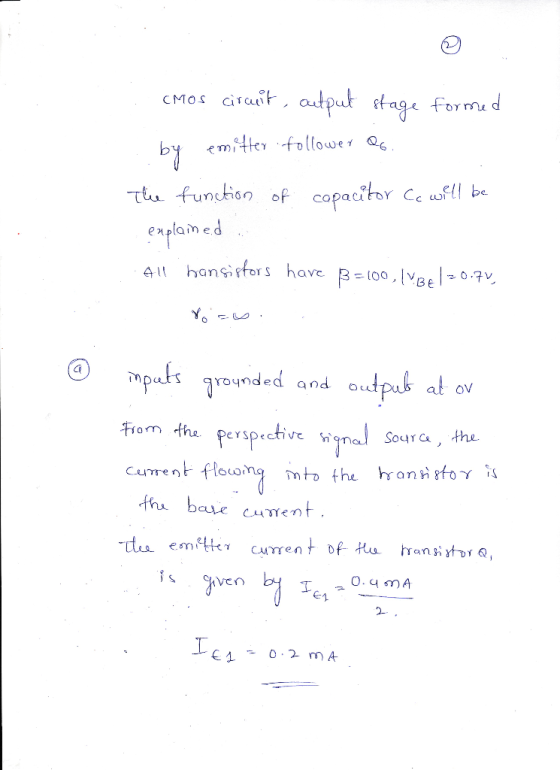
 This direct coupled emitter follower amplifier using a reference current mirror to produce a blasttent for the di transistor The parameters for the circuit are as follows: . Vcc = -Ves = 5V • All transistors. Qı, Q2, Qs, are matched with the following parameters + 8 = 100 , Is = 10- A (Hints: You must solve for for all transistors. You may need to lerate once or twice to solve the recent with the foresistor in the Qiraulties...
 Assume, VAfor differential pair transistors. Which of the following statements is incorrect? CO7 57.2 k VO3 VO2 C2 01 E6 REF E6 C3 V15V 04 V 15 V The differential stage is biased by basic 3 transistor current course (with double emitter on its output) Ideally Vo3 should be at 0.7V so that it produces a 0 output when there is no differential mode input signal. Gain of Vo3 Vd is approximately equal to 1 since it acts as emitter...
 The following figure shows the OP Amp circuit for a PID (Proportional-Integral-Derivative) controller. Find the transfer function of M(s) Y(s) Coefficient Gain Amplifier Rs Voltage Follower Summer.... Integrator 10 -m(t) Inverting (Power) ein Amplifier R7 Approximate Differentiator R.
The following figure shows the OP Amp circuit for a PID (Proportional-Integral-Derivative) controller. Find the transfer function of M(s) Y(s) Coefficient Gain Amplifier Rs Voltage Follower Summer.... Integrator 10 -m(t) Inverting (Power) ein Amplifier R7 Approximate Differentiator R.
The following figure shows the OP Amp circuit for a PID (Proportional-Integral-Derivative) controller. Find the transfer function of M(s) Y(s) Coefficient Gain Amplifier Rs Voltage Follower Summer.... Integrator 10 -m(t) Inverting (Power) ein Amplifier R7 Approximate Differentiator R.
 QUESTION 2: (20 MARKS) +5 V X2 71 QA X2 ×10 5 V Figure Q2.1 The circuit shown in Figure Q2.1, is a multistage amplifier with a differential input stage It uses a folded cascode involving transistor Q3. Note that transistor Q5 operates in class B mode and is off at the quiescent point, while Q4 is ON at the quiescent point with QD sinking its bias current. All transistors have Vad-0.7V, VA-200 V, and β-100 a) Perform a dc...
 Question 3. Unregulated supply Rz IL Vin IR Ib (a) The circuit on the right shows a series regulator connected to the output of an unregulated power supply. The transistor has B =50, and a 6 volt Zener diode is used. When the load current, Il, is 1 amp the de input voltage from the unregulated supply, Vin, is 11 volt, VBE = 1 volt and the Zener diode current, Iz, is 20 mA. For these conditions, calculate Iz (i)...
 Good morning, I need help with the following, they all relate to
OP Amps. Thanks in advance.
2 value 10.00 points Problem 05.010 An op amp voltage divider Find the voltage gain vo/vs of the circuit given below, where R1-18 kΩ and R2-14 k 2. 20 kΩ R1 1% R2 The voltage gain vo/vs of the circuit is Hints Referene eBook & Resources Hint#1 Check my work 3. 1000 points value Problem 05.025-Voltage follower Calculate the output voltage vo in...
Good morning, I need help with the following, they all relate to
OP Amps. Thanks in advance.
2 value 10.00 points Problem 05.010 An op amp voltage divider Find the voltage gain vo/vs of the circuit given below, where R1-18 kΩ and R2-14 k 2. 20 kΩ R1 1% R2 The voltage gain vo/vs of the circuit is Hints Referene eBook & Resources Hint#1 Check my work 3. 1000 points value Problem 05.025-Voltage follower Calculate the output voltage vo in...
 sedra smith book 7th edition chapter name is operational
amplifier. question 12.1 to 12.10 I need all solution with good
hand writing.
Problems 1075 Transistor Q3 WIL (um/um) 36/0.3 36/0.3 6/0.3 6/0.3 30/0.3 W/0.3 45/0.3 6/0.3 and A, if all devices are 0.3 m long, Q and Q2 are operated at overdrive voltages of 0.15-V magnitude, and Q is operated at Voy 0.2 V. Also, determine the op-amp output resistance 100 k2, C0.1 pF, G = 2 mA/V, R, =...
sedra smith book 7th edition chapter name is operational
amplifier. question 12.1 to 12.10 I need all solution with good
hand writing.
Problems 1075 Transistor Q3 WIL (um/um) 36/0.3 36/0.3 6/0.3 6/0.3 30/0.3 W/0.3 45/0.3 6/0.3 and A, if all devices are 0.3 m long, Q and Q2 are operated at overdrive voltages of 0.15-V magnitude, and Q is operated at Voy 0.2 V. Also, determine the op-amp output resistance 100 k2, C0.1 pF, G = 2 mA/V, R, =...
 3.1. For the BJT differential pair configuration shown below,
assume the input transistor beta is very large.
Then find the differential signal vd = vB1 − vB2 sufficient to
cause:
3.2. A differential amplifier resembling that below uses I =
200μA, RC = 10kohm and VCC = 3V. Assume beta is very large
3.4.For the emitter follower in the figure below, given VCC =
15 V, VEE = −15 V, RL = 1 kohm and beta = 100 for all...
3.1. For the BJT differential pair configuration shown below,
assume the input transistor beta is very large.
Then find the differential signal vd = vB1 − vB2 sufficient to
cause:
3.2. A differential amplifier resembling that below uses I =
200μA, RC = 10kohm and VCC = 3V. Assume beta is very large
3.4.For the emitter follower in the figure below, given VCC =
15 V, VEE = −15 V, RL = 1 kohm and beta = 100 for all...
 can
you do 4.83
Ar- Q Sea 100 V, what does the gain become? age at the collector. (b) Replacing the transistor by its T model, da the small-signal equivalent circuit of the a plifier. Analyze the resulting circuit to dete mine the voltage gain t/ 04.81 Consider the CE amplifier circuit of Fig. 4.43(a). It is required to design the circuit (i.e., find values for I and Rc) to meet the following specifications: (a) R,5kn (b) the voltage gain...
can
you do 4.83
Ar- Q Sea 100 V, what does the gain become? age at the collector. (b) Replacing the transistor by its T model, da the small-signal equivalent circuit of the a plifier. Analyze the resulting circuit to dete mine the voltage gain t/ 04.81 Consider the CE amplifier circuit of Fig. 4.43(a). It is required to design the circuit (i.e., find values for I and Rc) to meet the following specifications: (a) R,5kn (b) the voltage gain...
 Chapter 4, Problem 4.48 Design an op-amp circuit that has the following input/output relationship Vo 21V1+ 0.5V2 Use the circuit shown below: V20 RA R2 Vi If RB-1 k? and R 1-1 ks, find (a) RA and (b) R2. Click if you would like to Show Work for this question: Open Show Work
Most questions answered within 3 hours.
-
Where is the error in this code sequence?
String s1 = "Hello";
String s2 = "ello";...
asked 10 months ago -
Financial data for Joel de Paris, Inc., for last year
follow:
Joel de Paris, Inc.
Balance...
asked 10 months ago -
Consider this reaction:
Al2(SO4)3 (aq)+ BaCl3
(aq) Al2Cl6 (aq)- +
3BaSO4(s) . What is the...
asked 10 months ago -
Suppose that Savneet is considering increasing her
recent random sample from 20 car rentals to 40...
asked 10 months ago -
Trucks arrive at an unloading terminal at an average rate of 120
per hour.
Trucks arrive...
asked 10 months ago -
Why are methanol and ethanol completely soluble in water while
octanol is not very little soluble....
asked 10 months ago -
A facilities manager at a university reads in a research report
that the mean amount of...
asked 10 months ago -
When the CuSO4 is rehydrated by adding water to the anhydrous
compound, is this an endothermic...
asked 10 months ago -
A ray of sunlight is passing from diamond into crown glass; the
angle of incidence is...
asked 10 months ago -
A block of mass 0.249 kg is placed on top of a light, vertical
spring of...
asked 10 months ago -
how do the kidneys compensate in the presences of acidosis
a) trigger hyperventilate
b) reserve acid...
asked 10 months ago -
Question 501 pts
The rental rate of capital to the firm increases. Which of the
following...
asked 10 months ago