

Homework Answers


![६-२० ५ २०(3६-5) (E) - (३६-२०) २०( 3 ६-5] 158 - 7-8+२०६ ६-२० ६ ६ २०(38-5) 35६-25-82 (8६-२०) (35६-25-४६)- 6०६+ 16०६ ६ (35६-२5-8](http://img.homeworklib.com/questions/84c0d750-6b72-11ec-8907-eb758d3be7c2.png?x-oss-process=image/resize,w_560)


Add Answer to:
Q2 (a) List down THREE (3) important requirements to design a control system. (3 marks) State...
3. For the feedback control system shown in Figure Q3 below, the forward-path transfer function given...
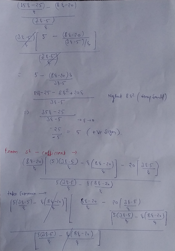
 3. For the feedback control system shown in Figure Q3 below, the forward-path transfer function given by G(s) and the sensor transfer function is given by H(s). R(s) C(s) G(s) H(s) Figure Q3 It is known that G(s) -- K(+20) S(+5) H(s) = and K is the proportional gain. (S+10) i. Determine the closed-loop transfer function and hence the characteristic equation of the system. [6 marks] ii. Using the Routh-Hurwitz criterion, determine the stability of the closed-loop system. Determine the...
Q4) (20 pts) c(s 5) 2(s) In the control system shown in the figure, i) Express...
 Q4) (20 pts) c(s 5) 2(s) In the control system shown in the figure, i) Express U(s) in terms of E (s). ii) Find the overall transfer function C2 and determine the characteristic equation. R(s) ii) Using Routh-Hurwitz method determine the range of values of K for stability
Q2. Fig Q2 shows the block diagram of an unstable system with transfer function G(s) -...
 Q2. Fig Q2 shows the block diagram of an unstable system with transfer function G(s) - under the control of a lead compensator (a) Using the Routh's stability criterion, determine the conditions on k and a so that the closed-loop system is stable, and sketch the region on the (k, a)- plane where the conditions are satisfied. Hence, determine the minimum value of k for the lead compensator to be a feasible stabilizing controller. (10 marks) (b) Suppose α-2. Given...
Question 6 The open-loop transfer function G(s) of a control system is given as G(8)- s(s+2)(s +5...
 Question 6 The open-loop transfer function G(s) of a control system is given as G(8)- s(s+2)(s +5) A proportional controller is used to control the system as shown in Figure 6 below: Y(s) R(s) + G(s) Figure 6: A control system with a proportional controller a) Assume Hp(s) is a proportional controller with the transfer function H,(s) kp. Determine, using the Routh-Hurwitz Stability Criterion, the value of kp for which the closed-loop system in Figure 6 is marginally stable. (6...
KKKM3473/KKKM3314/KKKM3344 The characteristic polynomial of a feedback control system is given by 5. where K>0. Dete...
 KKKM3473/KKKM3314/KKKM3344 The characteristic polynomial of a feedback control system is given by 5. where K>0. Determine the range of values of K for which the system is stable. (10 marks) The closed loop poles of a second order system are located at points -3.5+1.5t and 6. -3.5-1.51 on the complex plane. Calculate the damped natural frequency, ωd. (10 marks) 7. The Bode plots for a first order dynamic system is shown in Figure 3. Estimate the magnitude and phase when...
Question 2 Consider the system shown in Figure Q2, where Wis a unit step disturbance and R is a unit step input. 0.4 s+ 1 10 Figure Q2 (5 marks) (3 marks) (c) Find the value for K so that the steady...
 Question 2 Consider the system shown in Figure Q2, where Wis a unit step disturbance and R is a unit step input. 0.4 s+ 1 10 Figure Q2 (5 marks) (3 marks) (c) Find the value for K so that the steady state error due to w(t) is less than 0.01; 6 marks) (d) In order to eliminate the steady state error, show whether a PI controller can be successful 6 marks) (a) Find the expression of E(s)-R(s)-Y(s) in terms...
' 1. Review Question a) Name three applications for feedback control systems. b) Functionally, ho...
 ' 1. Review Question a) Name three applications for feedback control systems. b) Functionally, how do closed-loop systems differ from open-loop systems? c) Name the three major design criteria for control systems. d) Name the performance specification for first-order systems. e) Briefly describe how the zeros of the open-loop system affect the root locus and the transient response. What does the Routh-Hurwitz criterion tell us? f) 2. Given the electric network shown in Figure. a) Write the differential equation for...
Question 4 (a) A feedback control system with a proportional controller is shown in Figure Q4...
 Question 4 (a) A feedback control system with a proportional controller is shown in Figure Q4 (a). (i) Sketch the root locus of the system, (ii) Design the proportional controller (choose the value of K) such that the damping ratio does not exceed 0.5 and the time constant is less than 1 second. [All necessary steps of root locus construction and controller design must be shown). C(s) R(S) + s(s+4)(s + 10) Figure Q4 (a). A feedback control system [11...
Question 3 a) Develop the transfer function X2%)/F(s) of the mechanical system shown in Figure 3(a)....
 Question 3 a) Develop the transfer function X2%)/F(s) of the mechanical system shown in Figure 3(a). Give and explain one example the real application where you can relate with this system (5 marks) b) Routh's stability criterion is of limited usefulness in linear control systems analysis mainly because it does not suggest how to stabilize an unstable system. Thus, we should evaluate the stability range of a parameter value. Consider the servo system with tachometer feedback as shown in Figure...
 3. For the feedback control system shown in Figure Q3 below, the forward-path transfer function given by G(s) and the sensor transfer function is given by H(s). R(s) C(s) G(s) H(s) Figure Q3 It is known that G(s) -- K(+20) S(+5) H(s) = and K is the proportional gain. (S+10) i. Determine the closed-loop transfer function and hence the characteristic equation of the system. [6 marks] ii. Using the Routh-Hurwitz criterion, determine the stability of the closed-loop system. Determine the...
 Q4) (20 pts) c(s 5) 2(s) In the control system shown in the figure, i) Express U(s) in terms of E (s). ii) Find the overall transfer function C2 and determine the characteristic equation. R(s) ii) Using Routh-Hurwitz method determine the range of values of K for stability
 Q2. Fig Q2 shows the block diagram of an unstable system with transfer function G(s) - under the control of a lead compensator (a) Using the Routh's stability criterion, determine the conditions on k and a so that the closed-loop system is stable, and sketch the region on the (k, a)- plane where the conditions are satisfied. Hence, determine the minimum value of k for the lead compensator to be a feasible stabilizing controller. (10 marks) (b) Suppose α-2. Given...
 Question 6 The open-loop transfer function G(s) of a control system is given as G(8)- s(s+2)(s +5) A proportional controller is used to control the system as shown in Figure 6 below: Y(s) R(s) + G(s) Figure 6: A control system with a proportional controller a) Assume Hp(s) is a proportional controller with the transfer function H,(s) kp. Determine, using the Routh-Hurwitz Stability Criterion, the value of kp for which the closed-loop system in Figure 6 is marginally stable. (6...
 KKKM3473/KKKM3314/KKKM3344 The characteristic polynomial of a feedback control system is given by 5. where K>0. Determine the range of values of K for which the system is stable. (10 marks) The closed loop poles of a second order system are located at points -3.5+1.5t and 6. -3.5-1.51 on the complex plane. Calculate the damped natural frequency, ωd. (10 marks) 7. The Bode plots for a first order dynamic system is shown in Figure 3. Estimate the magnitude and phase when...
 Question 2 Consider the system shown in Figure Q2, where Wis a unit step disturbance and R is a unit step input. 0.4 s+ 1 10 Figure Q2 (5 marks) (3 marks) (c) Find the value for K so that the steady state error due to w(t) is less than 0.01; 6 marks) (d) In order to eliminate the steady state error, show whether a PI controller can be successful 6 marks) (a) Find the expression of E(s)-R(s)-Y(s) in terms...
 Question 2 Consider the system shown in Figure Q2, where Wis a unit step disturbance and R is a unit step input. 0.4 s+ 1 10 Figure Q2 (5 marks) (3 marks) (c) Find the value for K so that the steady state error due to w(t) is less than 0.01; 6 marks) (d) In order to eliminate the steady state error, show whether a PI controller can be successful 6 marks) (a) Find the expression of E(s)-R(s)-Y(s) in terms...
 ' 1. Review Question a) Name three applications for feedback control systems. b) Functionally, how do closed-loop systems differ from open-loop systems? c) Name the three major design criteria for control systems. d) Name the performance specification for first-order systems. e) Briefly describe how the zeros of the open-loop system affect the root locus and the transient response. What does the Routh-Hurwitz criterion tell us? f) 2. Given the electric network shown in Figure. a) Write the differential equation for...
 Question 4 (a) A feedback control system with a proportional controller is shown in Figure Q4 (a). (i) Sketch the root locus of the system, (ii) Design the proportional controller (choose the value of K) such that the damping ratio does not exceed 0.5 and the time constant is less than 1 second. [All necessary steps of root locus construction and controller design must be shown). C(s) R(S) + s(s+4)(s + 10) Figure Q4 (a). A feedback control system [11...
 Question 3 a) Develop the transfer function X2%)/F(s) of the mechanical system shown in Figure 3(a). Give and explain one example the real application where you can relate with this system (5 marks) b) Routh's stability criterion is of limited usefulness in linear control systems analysis mainly because it does not suggest how to stabilize an unstable system. Thus, we should evaluate the stability range of a parameter value. Consider the servo system with tachometer feedback as shown in Figure...
Most questions answered within 3 hours.
-
Where is the error in this code sequence?
String s1 = "Hello";
String s2 = "ello";...
asked 10 months ago -
Financial data for Joel de Paris, Inc., for last year
follow:
Joel de Paris, Inc.
Balance...
asked 10 months ago -
Consider this reaction:
Al2(SO4)3 (aq)+ BaCl3
(aq) Al2Cl6 (aq)- +
3BaSO4(s) . What is the...
asked 10 months ago -
Suppose that Savneet is considering increasing her
recent random sample from 20 car rentals to 40...
asked 10 months ago -
Trucks arrive at an unloading terminal at an average rate of 120
per hour.
Trucks arrive...
asked 10 months ago -
Why are methanol and ethanol completely soluble in water while
octanol is not very little soluble....
asked 10 months ago -
A facilities manager at a university reads in a research report
that the mean amount of...
asked 10 months ago -
When the CuSO4 is rehydrated by adding water to the anhydrous
compound, is this an endothermic...
asked 10 months ago -
A ray of sunlight is passing from diamond into crown glass; the
angle of incidence is...
asked 10 months ago -
A block of mass 0.249 kg is placed on top of a light, vertical
spring of...
asked 10 months ago -
how do the kidneys compensate in the presences of acidosis
a) trigger hyperventilate
b) reserve acid...
asked 10 months ago -
Question 501 pts
The rental rate of capital to the firm increases. Which of the
following...
asked 10 months ago