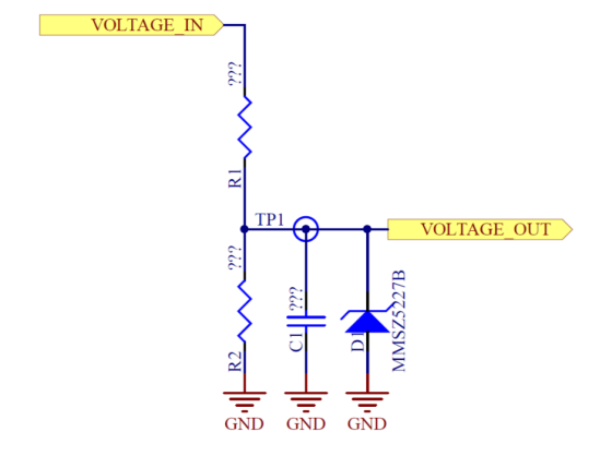
The figure is a voltage divider used to measure a signal that is expected to be in the 0V-50V range. Choose resistor values for R1 and R2 to allow an ADC with a +3.3V reference to accurately measure this input.
Homework Answers


Add Answer to:
The figure is a voltage divider used to measure a signal that is
expected to be...
Q1. You are given a 12 V DC power supply. You are expected to develop a voltage divider to achieve a voltage of no...
 Q1. You are given a 12 V DC power supply. You are expected to develop a voltage divider to achieve a voltage of nominal 5V value using a pair of resistors from the E 12 range, with the restrition that you are not expected to draw a current of more than 1 mA from the 12 V DC supply i. Develop a simple circuit showing the possible values for each resistor pair, and the range of the DC output possible...
Problem 1: Signal conditioning and ADC Given the measurement of voltage sensor in the first 20 ms that involving a seve...
 Problem 1: Signal conditioning and ADC Given the measurement of voltage sensor in the first 20 ms that involving a several noises causes a drift in measurement. The measurement signal fluctuates with time as a sine wave [sin(wt), ω in rad/s, t in ms] which can be approximately divided into four sections as in the following table Section I Section II on III 9St<13.2 Section IV Time (ms)OSt<5.5 Signal (volt) V-0.5+0.1 5.5 St<9 13.2 Sts20.5 V-0.6+0.1 V-0.55+0.1 V-0.65+0.1 sin(3.41x 10³t)...
Question 6 Determine lp and Vas for the JFET with voltage-divider bias in figure 6, given...
 Question 6 Determine lp and Vas for the JFET with voltage-divider bias in figure 6, given that for this particular JFET the parameter values are such that V 5V VDD 12V R1 RD 3.3k2 R2 1 ΟΜΩ Figure 6
to create a circuit which drives a controlled current through an LED with an input voltage,...
 to create a circuit which drives a controlled current through an
LED with an
input voltage, Vref.The design performed here is a low power
circuit (at most 15 mA
ows through the LED) which will be scaled up to a high
powered version (300 mA) for your major project.
The voltage drop across the resistor should be large enough for
the feedback voltage to not
be signicantly e ected by noise.
The resistance should be large enough for parasitic resistance...
to create a circuit which drives a controlled current through an
LED with an
input voltage, Vref.The design performed here is a low power
circuit (at most 15 mA
ows through the LED) which will be scaled up to a high
powered version (300 mA) for your major project.
The voltage drop across the resistor should be large enough for
the feedback voltage to not
be signicantly e ected by noise.
The resistance should be large enough for parasitic resistance...
Exercise #4 Voltage Divider A. Introduction In a previous exercise, you learned about the current-voltage relationship...
 Exercise #4 Voltage Divider A. Introduction In a previous exercise, you learned about the current-voltage relationship in a single resistor. Now, you will about how voltage is divided across two resistors in series. In this exercise you will: Examine the operation of the electric circuit known as the voltape divicder At the conclusion of this exercise you should be able to Compute the valtage across a resistor in a voltage divider circuit Design a voltage divider circuit to produce a...
8.) In the OP amp circuit shown in Figure 8 , determine the value of resistor...
 8.) In the OP amp circuit shown in Figure 8 , determine the
value of resistor R2 needed to establish an input trip point
voltage of 6.75 Volts ( i.e. when input signal voltage V in exceeds
6.75 V the OP amp’s output voltage changes state ) . ( 60 pts )
R2 = _______________
If the OP AMP in Figure 8 was biased by DC voltages of + / - 15
Volts , and the value of resistor R2...
8.) In the OP amp circuit shown in Figure 8 , determine the
value of resistor R2 needed to establish an input trip point
voltage of 6.75 Volts ( i.e. when input signal voltage V in exceeds
6.75 V the OP amp’s output voltage changes state ) . ( 60 pts )
R2 = _______________
If the OP AMP in Figure 8 was biased by DC voltages of + / - 15
Volts , and the value of resistor R2...
1. As a reference, observe the full amplitude range of the AC voltage, without limiting. R1...
 1. As a reference, observe the full amplitude range of the AC voltage, without limiting. R1 330 0 f=1.0 kHz 3.0 k2 out Vap = 15.0 V Figure 1. AC Circuit without limiter Construct the circuit of Figure 1. Set the function generator for a sine wave with a frequency of about 1 kHz. Begin with the AC input voltage adjusted to its minimum value, approximately 0 V. Connect Channel 1 of the oscilloscope to observe the AC input voltag...
The circuit below can be used to simulate/measure the equivalent resistance of a circuit. The voltage...
 The circuit below can be used to simulate/measure the equivalent resistance of a circuit. The voltage from V, to ground will be the equivalent resistance because V-IR and in this case the current source ll is equal to 1 Amp. Note that in general Amp.s not used by a resistance meter as it can cause a too much power to be dissipated by the resistor which can burn out the resistor or change its value.) Create the circuit shown below...
The circuit 3-The circuit of problem # 2 is subjected to a small ac input by the signal generator. By neglecting the voltage drop across the coupling and bypass capacitors, determine the small signa...
 The circuit
3-The circuit of problem # 2 is subjected to a small ac input by the signal generator. By neglecting the voltage drop across the coupling and bypass capacitors, determine the small signal voltage gain Vo/ Vì = Avi , input resistance Ri-vi / ii and the output resistance Ro external to R Avi= Ri= , Ro The accompanying circuit shows a 4-resistor biased JFET transistor Determine the values of Rp and Rs so that the Q-point is equal...
The circuit
3-The circuit of problem # 2 is subjected to a small ac input by the signal generator. By neglecting the voltage drop across the coupling and bypass capacitors, determine the small signal voltage gain Vo/ Vì = Avi , input resistance Ri-vi / ii and the output resistance Ro external to R Avi= Ri= , Ro The accompanying circuit shows a 4-resistor biased JFET transistor Determine the values of Rp and Rs so that the Q-point is equal...
Question #1 (20 pts.) (Begin your solution on a new page) a-(15 pts) The voltage divider...
 Question #1 (20 pts.) (Begin your solution on a new page) a-(15 pts) The voltage divider shown below is comprised of a stable 45.00 volt source and three, 1/4 watt, 1 KQ resistors with a tolerance of 5%. What is the nominal output voltage, Vout, as well as the range of voltages that you might expect? b-c4pts) Assuming nominal values, what is the total power dissipated in the circuit? C- (1 pt) Are these resistors an appropriate choice for this...
 Q1. You are given a 12 V DC power supply. You are expected to develop a voltage divider to achieve a voltage of nominal 5V value using a pair of resistors from the E 12 range, with the restrition that you are not expected to draw a current of more than 1 mA from the 12 V DC supply i. Develop a simple circuit showing the possible values for each resistor pair, and the range of the DC output possible...
 Problem 1: Signal conditioning and ADC Given the measurement of voltage sensor in the first 20 ms that involving a several noises causes a drift in measurement. The measurement signal fluctuates with time as a sine wave [sin(wt), ω in rad/s, t in ms] which can be approximately divided into four sections as in the following table Section I Section II on III 9St<13.2 Section IV Time (ms)OSt<5.5 Signal (volt) V-0.5+0.1 5.5 St<9 13.2 Sts20.5 V-0.6+0.1 V-0.55+0.1 V-0.65+0.1 sin(3.41x 10³t)...
 Question 6 Determine lp and Vas for the JFET with voltage-divider bias in figure 6, given that for this particular JFET the parameter values are such that V 5V VDD 12V R1 RD 3.3k2 R2 1 ΟΜΩ Figure 6
 to create a circuit which drives a controlled current through an
LED with an
input voltage, Vref.The design performed here is a low power
circuit (at most 15 mA
ows through the LED) which will be scaled up to a high
powered version (300 mA) for your major project.
The voltage drop across the resistor should be large enough for
the feedback voltage to not
be signicantly e ected by noise.
The resistance should be large enough for parasitic resistance...
to create a circuit which drives a controlled current through an
LED with an
input voltage, Vref.The design performed here is a low power
circuit (at most 15 mA
ows through the LED) which will be scaled up to a high
powered version (300 mA) for your major project.
The voltage drop across the resistor should be large enough for
the feedback voltage to not
be signicantly e ected by noise.
The resistance should be large enough for parasitic resistance...
 Exercise #4 Voltage Divider A. Introduction In a previous exercise, you learned about the current-voltage relationship in a single resistor. Now, you will about how voltage is divided across two resistors in series. In this exercise you will: Examine the operation of the electric circuit known as the voltape divicder At the conclusion of this exercise you should be able to Compute the valtage across a resistor in a voltage divider circuit Design a voltage divider circuit to produce a...
 8.) In the OP amp circuit shown in Figure 8 , determine the
value of resistor R2 needed to establish an input trip point
voltage of 6.75 Volts ( i.e. when input signal voltage V in exceeds
6.75 V the OP amp’s output voltage changes state ) . ( 60 pts )
R2 = _______________
If the OP AMP in Figure 8 was biased by DC voltages of + / - 15
Volts , and the value of resistor R2...
8.) In the OP amp circuit shown in Figure 8 , determine the
value of resistor R2 needed to establish an input trip point
voltage of 6.75 Volts ( i.e. when input signal voltage V in exceeds
6.75 V the OP amp’s output voltage changes state ) . ( 60 pts )
R2 = _______________
If the OP AMP in Figure 8 was biased by DC voltages of + / - 15
Volts , and the value of resistor R2...
 1. As a reference, observe the full amplitude range of the AC voltage, without limiting. R1 330 0 f=1.0 kHz 3.0 k2 out Vap = 15.0 V Figure 1. AC Circuit without limiter Construct the circuit of Figure 1. Set the function generator for a sine wave with a frequency of about 1 kHz. Begin with the AC input voltage adjusted to its minimum value, approximately 0 V. Connect Channel 1 of the oscilloscope to observe the AC input voltag...
 The circuit below can be used to simulate/measure the equivalent resistance of a circuit. The voltage from V, to ground will be the equivalent resistance because V-IR and in this case the current source ll is equal to 1 Amp. Note that in general Amp.s not used by a resistance meter as it can cause a too much power to be dissipated by the resistor which can burn out the resistor or change its value.) Create the circuit shown below...
 The circuit
3-The circuit of problem # 2 is subjected to a small ac input by the signal generator. By neglecting the voltage drop across the coupling and bypass capacitors, determine the small signal voltage gain Vo/ Vì = Avi , input resistance Ri-vi / ii and the output resistance Ro external to R Avi= Ri= , Ro The accompanying circuit shows a 4-resistor biased JFET transistor Determine the values of Rp and Rs so that the Q-point is equal...
The circuit
3-The circuit of problem # 2 is subjected to a small ac input by the signal generator. By neglecting the voltage drop across the coupling and bypass capacitors, determine the small signal voltage gain Vo/ Vì = Avi , input resistance Ri-vi / ii and the output resistance Ro external to R Avi= Ri= , Ro The accompanying circuit shows a 4-resistor biased JFET transistor Determine the values of Rp and Rs so that the Q-point is equal...
 Question #1 (20 pts.) (Begin your solution on a new page) a-(15 pts) The voltage divider shown below is comprised of a stable 45.00 volt source and three, 1/4 watt, 1 KQ resistors with a tolerance of 5%. What is the nominal output voltage, Vout, as well as the range of voltages that you might expect? b-c4pts) Assuming nominal values, what is the total power dissipated in the circuit? C- (1 pt) Are these resistors an appropriate choice for this...
Most questions answered within 3 hours.
-
Where is the error in this code sequence?
String s1 = "Hello";
String s2 = "ello";...
asked 11 months ago -
Financial data for Joel de Paris, Inc., for last year
follow:
Joel de Paris, Inc.
Balance...
asked 11 months ago -
Consider this reaction:
Al2(SO4)3 (aq)+ BaCl3
(aq) Al2Cl6 (aq)- +
3BaSO4(s) . What is the...
asked 11 months ago -
Suppose that Savneet is considering increasing her
recent random sample from 20 car rentals to 40...
asked 11 months ago -
Trucks arrive at an unloading terminal at an average rate of 120
per hour.
Trucks arrive...
asked 11 months ago -
Why are methanol and ethanol completely soluble in water while
octanol is not very little soluble....
asked 11 months ago -
A facilities manager at a university reads in a research report
that the mean amount of...
asked 11 months ago -
When the CuSO4 is rehydrated by adding water to the anhydrous
compound, is this an endothermic...
asked 11 months ago -
A ray of sunlight is passing from diamond into crown glass; the
angle of incidence is...
asked 11 months ago -
A block of mass 0.249 kg is placed on top of a light, vertical
spring of...
asked 11 months ago -
how do the kidneys compensate in the presences of acidosis
a) trigger hyperventilate
b) reserve acid...
asked 11 months ago -
Question 501 pts
The rental rate of capital to the firm increases. Which of the
following...
asked 11 months ago