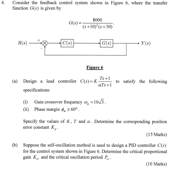
Please explain the steps taken in detail for both part a) and b). Thank you very much.
Homework Answers


Add Answer to:
Please explain the steps taken in detail for both part a) and
b). Thank you very...
Question 6 The open-loop transfer function G(s) of a control system is given as G(8)- s(s+2)(s +5...
 Question 6 The open-loop transfer function G(s) of a control system is given as G(8)- s(s+2)(s +5) A proportional controller is used to control the system as shown in Figure 6 below: Y(s) R(s) + G(s) Figure 6: A control system with a proportional controller a) Assume Hp(s) is a proportional controller with the transfer function H,(s) kp. Determine, using the Routh-Hurwitz Stability Criterion, the value of kp for which the closed-loop system in Figure 6 is marginally stable. (6...
Question 3 (10 +10+10+15 45 marks) E(s) C(s) R(s) Figure 3: Unity feedback control system for Question 3 For the unity...
 Question 3 (10 +10+10+15 45 marks) E(s) C(s) R(s) Figure 3: Unity feedback control system for Question 3 For the unity feedback control system shown in Figure 3, 100 G(S) (s+2)(+10) Page 3 of 7 NEE3201 Examination Paper CRICOS Provider No: 00124k a) Determine the phase margin, the gain crossover frequency, the gain margin, the phase crossover frequency of the system when Gc(s)-1, 10 marks) b) Design a proportional controller Gc(s)-K so that a phase margin of 50° is achieved....
Please explain part b and C in detail. Figure 6 shows a feedback control system for...
 Please explain part b and C in detail.
Figure 6 shows a feedback control system for which G(s) = 6 (s + 1)3 J' and K(s) is the transfer function of a compensator. (a) Sketch the Nyquist diagram of G(s) evaluating the real-axis intercepts and their corre- sponding frequencies. [10 marks] (b) Show that the closed-loop system will oscillate at frequency w = V3 rad s-1 when the closed-loop gain is K = ? (5 marks] (c) Design a proportional-derivative...
Please explain part b and C in detail.
Figure 6 shows a feedback control system for which G(s) = 6 (s + 1)3 J' and K(s) is the transfer function of a compensator. (a) Sketch the Nyquist diagram of G(s) evaluating the real-axis intercepts and their corre- sponding frequencies. [10 marks] (b) Show that the closed-loop system will oscillate at frequency w = V3 rad s-1 when the closed-loop gain is K = ? (5 marks] (c) Design a proportional-derivative...
[7] Sketch the root locus for the unity feedback system whose open loop transfer function is K G(s) Draw the root lo...
 [7] Sketch the root locus for the unity feedback system whose open loop transfer function is K G(s) Draw the root locus of the system with the gain Kas a variable. s(s+4) (s2+4s+20) Determine asymptotes, centroid, breakaway point, angle of departure, and the gain at which root locus crosses ja-axis. A control system with type-0 process and a PID controller is shown below. Design the [8 parameters of the PID controller so that the following specifications are satisfied. =100 a)...
G) r(t) Figure 1: Feedback control system A pulley and belt transmission has a linearized relationship between the driven pulley angle θ(t) in degrees and the input torque u(t) in Newton meters given...
 G) r(t) Figure 1: Feedback control system A pulley and belt transmission has a linearized relationship between the driven pulley angle θ(t) in degrees and the input torque u(t) in Newton meters given by the following differential equation du(t) A feedback control system (illustrated in Figure 1) needs to be designed such that the closed-loop system is asymptotically stable and such that the following design criteria are met: 1. the gain crossover frequency a should be between and a 2....
Implement a PID controller to control the transfer function shown below. The PID controller and plant...
 Implement a PID controller to control the transfer function
shown below. The PID controller and plant transfer function should
be in a closed feedback loop. Assume the feedback loop has a Gain
of 5 associated with it i.e. . The Transfer function of a PID
controller is also given below. Start by:
6. Implement a PID controller to control the transfer function shown below. The PID feedback loop has a Gain of 5 associated with it i.e. (HS) = 5)....
Implement a PID controller to control the transfer function
shown below. The PID controller and plant transfer function should
be in a closed feedback loop. Assume the feedback loop has a Gain
of 5 associated with it i.e. . The Transfer function of a PID
controller is also given below. Start by:
6. Implement a PID controller to control the transfer function shown below. The PID feedback loop has a Gain of 5 associated with it i.e. (HS) = 5)....
Consider the transfer function of a DC motor given by G(s) = 1 / s(s+2) 3. Consider the transfer function of a DC motor...
 Consider the transfer function of a DC motor given by G(s) = 1 /
s(s+2)
3. Consider the transfer function of a DC motor given by 1 G(s) s (s2) The objective of this question is to consider the problem of control design for this DC motor, with the feedback control architecture shown in the figure below d(t r(t) e(t) e(t) C(s) G(s) Figure 4: A feedback control system (a) Find the magnitude and the phase of the frequency response...
Consider the transfer function of a DC motor given by G(s) = 1 /
s(s+2)
3. Consider the transfer function of a DC motor given by 1 G(s) s (s2) The objective of this question is to consider the problem of control design for this DC motor, with the feedback control architecture shown in the figure below d(t r(t) e(t) e(t) C(s) G(s) Figure 4: A feedback control system (a) Find the magnitude and the phase of the frequency response...
3. For the feedback control system shown in Figure Q3 below, the forward-path transfer function given...
 3. For the feedback control system shown in Figure Q3 below, the forward-path transfer function given by G(s) and the sensor transfer function is given by H(s). R(s) C(s) G(s) H(s) Figure Q3 It is known that G(s) -- K(+20) S(+5) H(s) = and K is the proportional gain. (S+10) i. Determine the closed-loop transfer function and hence the characteristic equation of the system. [6 marks] ii. Using the Routh-Hurwitz criterion, determine the stability of the closed-loop system. Determine the...
1. Consider the following feedback control system Controller Process 1 G(s) R(s) Y(s) $2+5s+6 Below are...
 1. Consider the following feedback control system Controller Process 1 G(s) R(s) Y(s) $2+5s+6 Below are two potential controllers for this system: 1) Ge(s) K (Proportional controller) 2) Ge(s) K(1 1/s) (Proportional-integral controller) The design specifications are t 3.2s and P. 0. 10% for a unit step input (a) Determine the area on the S-plane where the dominant closed loop poles must be located such that the design requirements are satisfied. (b) Sketch the root locus with each of the...
new question as i don’t have extra information and better quality of the pic for previous...
 new question as i don’t have extra information and better
quality of the pic for previous question
Question 2 (20 marks) The feed forwand transfer function of an automated manufacturing process is given by K(s+3) 1-1S(5)9 where K is the proportional controller gain. The root locus is shown in Figure 6 a) Determine the range of values of K for which the closed loop system will exhibis a (10 marks) b) Determine a value of K that gives a damping...
new question as i don’t have extra information and better
quality of the pic for previous question
Question 2 (20 marks) The feed forwand transfer function of an automated manufacturing process is given by K(s+3) 1-1S(5)9 where K is the proportional controller gain. The root locus is shown in Figure 6 a) Determine the range of values of K for which the closed loop system will exhibis a (10 marks) b) Determine a value of K that gives a damping...
 Question 6 The open-loop transfer function G(s) of a control system is given as G(8)- s(s+2)(s +5) A proportional controller is used to control the system as shown in Figure 6 below: Y(s) R(s) + G(s) Figure 6: A control system with a proportional controller a) Assume Hp(s) is a proportional controller with the transfer function H,(s) kp. Determine, using the Routh-Hurwitz Stability Criterion, the value of kp for which the closed-loop system in Figure 6 is marginally stable. (6...
 Question 3 (10 +10+10+15 45 marks) E(s) C(s) R(s) Figure 3: Unity feedback control system for Question 3 For the unity feedback control system shown in Figure 3, 100 G(S) (s+2)(+10) Page 3 of 7 NEE3201 Examination Paper CRICOS Provider No: 00124k a) Determine the phase margin, the gain crossover frequency, the gain margin, the phase crossover frequency of the system when Gc(s)-1, 10 marks) b) Design a proportional controller Gc(s)-K so that a phase margin of 50° is achieved....
 Please explain part b and C in detail.
Figure 6 shows a feedback control system for which G(s) = 6 (s + 1)3 J' and K(s) is the transfer function of a compensator. (a) Sketch the Nyquist diagram of G(s) evaluating the real-axis intercepts and their corre- sponding frequencies. [10 marks] (b) Show that the closed-loop system will oscillate at frequency w = V3 rad s-1 when the closed-loop gain is K = ? (5 marks] (c) Design a proportional-derivative...
Please explain part b and C in detail.
Figure 6 shows a feedback control system for which G(s) = 6 (s + 1)3 J' and K(s) is the transfer function of a compensator. (a) Sketch the Nyquist diagram of G(s) evaluating the real-axis intercepts and their corre- sponding frequencies. [10 marks] (b) Show that the closed-loop system will oscillate at frequency w = V3 rad s-1 when the closed-loop gain is K = ? (5 marks] (c) Design a proportional-derivative...
 [7] Sketch the root locus for the unity feedback system whose open loop transfer function is K G(s) Draw the root locus of the system with the gain Kas a variable. s(s+4) (s2+4s+20) Determine asymptotes, centroid, breakaway point, angle of departure, and the gain at which root locus crosses ja-axis. A control system with type-0 process and a PID controller is shown below. Design the [8 parameters of the PID controller so that the following specifications are satisfied. =100 a)...
 G) r(t) Figure 1: Feedback control system A pulley and belt transmission has a linearized relationship between the driven pulley angle θ(t) in degrees and the input torque u(t) in Newton meters given by the following differential equation du(t) A feedback control system (illustrated in Figure 1) needs to be designed such that the closed-loop system is asymptotically stable and such that the following design criteria are met: 1. the gain crossover frequency a should be between and a 2....
 Implement a PID controller to control the transfer function
shown below. The PID controller and plant transfer function should
be in a closed feedback loop. Assume the feedback loop has a Gain
of 5 associated with it i.e. . The Transfer function of a PID
controller is also given below. Start by:
6. Implement a PID controller to control the transfer function shown below. The PID feedback loop has a Gain of 5 associated with it i.e. (HS) = 5)....
Implement a PID controller to control the transfer function
shown below. The PID controller and plant transfer function should
be in a closed feedback loop. Assume the feedback loop has a Gain
of 5 associated with it i.e. . The Transfer function of a PID
controller is also given below. Start by:
6. Implement a PID controller to control the transfer function shown below. The PID feedback loop has a Gain of 5 associated with it i.e. (HS) = 5)....
 Consider the transfer function of a DC motor given by G(s) = 1 /
s(s+2)
3. Consider the transfer function of a DC motor given by 1 G(s) s (s2) The objective of this question is to consider the problem of control design for this DC motor, with the feedback control architecture shown in the figure below d(t r(t) e(t) e(t) C(s) G(s) Figure 4: A feedback control system (a) Find the magnitude and the phase of the frequency response...
Consider the transfer function of a DC motor given by G(s) = 1 /
s(s+2)
3. Consider the transfer function of a DC motor given by 1 G(s) s (s2) The objective of this question is to consider the problem of control design for this DC motor, with the feedback control architecture shown in the figure below d(t r(t) e(t) e(t) C(s) G(s) Figure 4: A feedback control system (a) Find the magnitude and the phase of the frequency response...
 3. For the feedback control system shown in Figure Q3 below, the forward-path transfer function given by G(s) and the sensor transfer function is given by H(s). R(s) C(s) G(s) H(s) Figure Q3 It is known that G(s) -- K(+20) S(+5) H(s) = and K is the proportional gain. (S+10) i. Determine the closed-loop transfer function and hence the characteristic equation of the system. [6 marks] ii. Using the Routh-Hurwitz criterion, determine the stability of the closed-loop system. Determine the...
 1. Consider the following feedback control system Controller Process 1 G(s) R(s) Y(s) $2+5s+6 Below are two potential controllers for this system: 1) Ge(s) K (Proportional controller) 2) Ge(s) K(1 1/s) (Proportional-integral controller) The design specifications are t 3.2s and P. 0. 10% for a unit step input (a) Determine the area on the S-plane where the dominant closed loop poles must be located such that the design requirements are satisfied. (b) Sketch the root locus with each of the...
 new question as i don’t have extra information and better
quality of the pic for previous question
Question 2 (20 marks) The feed forwand transfer function of an automated manufacturing process is given by K(s+3) 1-1S(5)9 where K is the proportional controller gain. The root locus is shown in Figure 6 a) Determine the range of values of K for which the closed loop system will exhibis a (10 marks) b) Determine a value of K that gives a damping...
new question as i don’t have extra information and better
quality of the pic for previous question
Question 2 (20 marks) The feed forwand transfer function of an automated manufacturing process is given by K(s+3) 1-1S(5)9 where K is the proportional controller gain. The root locus is shown in Figure 6 a) Determine the range of values of K for which the closed loop system will exhibis a (10 marks) b) Determine a value of K that gives a damping...
Most questions answered within 3 hours.
-
Where is the error in this code sequence?
String s1 = "Hello";
String s2 = "ello";...
asked 10 months ago -
Financial data for Joel de Paris, Inc., for last year
follow:
Joel de Paris, Inc.
Balance...
asked 10 months ago -
Consider this reaction:
Al2(SO4)3 (aq)+ BaCl3
(aq) Al2Cl6 (aq)- +
3BaSO4(s) . What is the...
asked 10 months ago -
Suppose that Savneet is considering increasing her
recent random sample from 20 car rentals to 40...
asked 10 months ago -
Trucks arrive at an unloading terminal at an average rate of 120
per hour.
Trucks arrive...
asked 10 months ago -
Why are methanol and ethanol completely soluble in water while
octanol is not very little soluble....
asked 10 months ago -
A facilities manager at a university reads in a research report
that the mean amount of...
asked 10 months ago -
When the CuSO4 is rehydrated by adding water to the anhydrous
compound, is this an endothermic...
asked 10 months ago -
A ray of sunlight is passing from diamond into crown glass; the
angle of incidence is...
asked 10 months ago -
A block of mass 0.249 kg is placed on top of a light, vertical
spring of...
asked 10 months ago -
how do the kidneys compensate in the presences of acidosis
a) trigger hyperventilate
b) reserve acid...
asked 10 months ago -
Question 501 pts
The rental rate of capital to the firm increases. Which of the
following...
asked 10 months ago