
Homework Answers
Answers
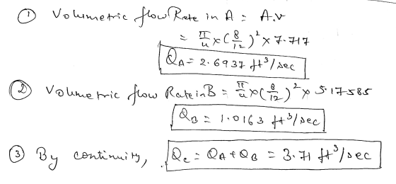
1. 2.6937
2. 1.0163
3. 3.71
4. 1101.948


Add Answer to:
For the System below answer the following: Hints: VA=1.134Vc and Va=1.491VB Pipe D(in) L(ft) f A...
(25pts) The 0.5in.-diameter hose shown in Figure can withstand a maximum pressure of 300 psi without...
 (25pts) The 0.5in.-diameter hose shown in Figure can withstand a maximum pressure of 300 psi without rupturing. Determine the maximum length, 1, allowed if the friction factor is 0.022 and the flowrate is 0.020 f/s. Neglect minor losses Nozzle tip diameter - 0.30 in. y = 62.2 lb/ft3 D-0.50 in. P2 = 0 Water 10 ft 3 ft Pump
Problem 1: In the reservoir-pipe system below, water is supplied from reservoir A to reservoir B...
 Problem 1: In the reservoir-pipe system below, water is supplied from reservoir A to reservoir B with a flowrate of 50 L/S. In the system, a pump with an efficiency value of n=0.70 is used. Length of the pipeline is L=5000m, pipe diameter is D=200 mm and the elevation difference between reservoirs is 40 m. According to this, a) Determine the required pump head (Hp). b) Find the required nominal pump power. c) Draw the relative energy grade line of...
1) 2) 3) Oil flows through an 8-inch diameter pipe with a velocity of 18 ft/s....
 1)
2)
3)
Oil flows through an 8-inch diameter pipe with a velocity of 18 ft/s. If it discharges into the atmosphere through the nozzle, determine the total force the bolts must resist at the connection AB to hold the nozzle onto the pipe. Assume Yo = 55 lb/ft3. (30 pts) 8 in. 4 in. 18 m/s 06 PROB011 Research is being conducted on a medical specimen. They are trying to determine the pressure drop in fluid carrying vessels. If...
1)
2)
3)
Oil flows through an 8-inch diameter pipe with a velocity of 18 ft/s. If it discharges into the atmosphere through the nozzle, determine the total force the bolts must resist at the connection AB to hold the nozzle onto the pipe. Assume Yo = 55 lb/ft3. (30 pts) 8 in. 4 in. 18 m/s 06 PROB011 Research is being conducted on a medical specimen. They are trying to determine the pressure drop in fluid carrying vessels. If...
Net ID Date. Name 3. For the pipe system illustrated below A. For the pipes, complete the followi...
 Net ID Date. Name 3. For the pipe system illustrated below A. For the pipes, complete the following table (compute the head losses, flows and velocities for pipes B and C) IA(fn -tales 215001018이 (in) A(t)Q(fs) 8 0.34907 60.19635 4 0.08727 Pipe 6.188 002 8.926 6000 11000」 9000 4000 002 0 02 0.34907 2.1599 6.188002 5 951 B. Compute the pressure (in psi) at junction J-1 (at an elevation of 270 t). WSE 300 ft f-0.02 all lines B. EL...
Water with density of p=1.94 slug/ft3 and dynamic viscosity of 2.34X10⁻⁵ slug/ft.s flows from the basement...
 Water with density of p=1.94 slug/ft3 and dynamic viscosity of 2.34X10⁻⁵ slug/ft.s flows from the basement to the second floor through the 0.75 in (0.0625 ft)-diameter copper pipe (a drawn tubing wit e=0.000005 ft) at a rate of Q=12.0 gal/min=0.0267 ft3/s and exits through a faucet of diameter 0.50 in. as shown in the figure K1 = 2 based on pipe velocity -10 ft- 10 ft (7)|(8) (2) (6) 0.75-in.-diameter copper pipe 5 ft 10 ft Wide open globe valve...
Name Net ID Date: 3. For the pipe system illustrated below A. For the pipes, complete...
 Name Net ID Date: 3. For the pipe system illustrated below A. For the pipes, complete the following table (compute the head losses flows and velocities for pipes B and C) Pipe L(t) D (in) A (ft) 8 0.34907 6 0.19635 4 0.08727 80.34907 Q (cfs) 2.1599 6,188 002 8 926 11000 0.02 0.02 2.1599 6.188 002 5951 4000 B. Compute the pressure (in psi) at junction J-1 (at an elevation of 270 WSE 300 ft f-o 02 all lines...
3. A car's exhaust system is approximated a system is composed by six 90 flanged elbows muffler respectively. The exhaust flow is o.1 ft/s and has the same ted as a cast iron pipe system ori4 n i...
 3. A car's exhaust system is approximated a system is composed by six 90 flanged elbows muffler respectively. The exhaust flow is o.1 ft/s and has the same ted as a cast iron pipe system ori4 n iength, 0.09-ft-diameter, and ε 0.00085/t. This and a muffler where each accessory has a minor losses coefficient of O.3 and 8s property than air (density 1.74 10 slug/ft.viscosity 4.7-10b's/ sure at section 1.Hint: Neglect the elevati on change Az for gases, (Objective 6.3...
4. An old, rough-surfaced, 2-m-diameter concrete pipe with a Manning coefficient of 0.025 carries water at...
 4. An old, rough-surfaced, 2-m-diameter concrete pipe with a Manning coefficient of 0.025 carries water at a rate of 5.0 m'/s when it is half ful. This pipe is to be replaced by a new smooth pipe with a Manning coefficient of 0.012. Determine the diameter of the new pipe if it also is to flow half full with a flow rate of 5.0 m'/s Water initially flowing in the horizontal section of pipe of diameter 12.00 cm shown in...
3. The water flow in the concrete pipe looping system shown in the figure below is...
 3. The water flow in the concrete pipe looping system shown in the figure below is 15 ft/s. Compute the head loss from point A to point G. Temp of water -20° C. 1500 ft, 18-in diameter B A- 2500 ft, 30-in diameter Q= 15 ft/sec 2000 ft, 15-in diameter Q = 15 ft/sec - G 1000 ft, 12-in diameter C 2000 ft, 15-in diameter
The figure below shows a condenser/cooling tower pipe system needed to remove heat from a water...
 The figure below shows a condenser/cooling tower pipe system needed to remove heat from a water cooled refrigeration condenser and reject the heat to the atmosphere. The amount of heat to be rejected to the atmosphere is 480,000 Btu/hr. The water enters the condenser at 85"F, and the temperature rise of the water through the condenser is 10°F. The total length of the piping in the system is 60 ft. Fittings are as shown. Assume bends to be as shown...
 (25pts) The 0.5in.-diameter hose shown in Figure can withstand a maximum pressure of 300 psi without rupturing. Determine the maximum length, 1, allowed if the friction factor is 0.022 and the flowrate is 0.020 f/s. Neglect minor losses Nozzle tip diameter - 0.30 in. y = 62.2 lb/ft3 D-0.50 in. P2 = 0 Water 10 ft 3 ft Pump
 Problem 1: In the reservoir-pipe system below, water is supplied from reservoir A to reservoir B with a flowrate of 50 L/S. In the system, a pump with an efficiency value of n=0.70 is used. Length of the pipeline is L=5000m, pipe diameter is D=200 mm and the elevation difference between reservoirs is 40 m. According to this, a) Determine the required pump head (Hp). b) Find the required nominal pump power. c) Draw the relative energy grade line of...
 1)
2)
3)
Oil flows through an 8-inch diameter pipe with a velocity of 18 ft/s. If it discharges into the atmosphere through the nozzle, determine the total force the bolts must resist at the connection AB to hold the nozzle onto the pipe. Assume Yo = 55 lb/ft3. (30 pts) 8 in. 4 in. 18 m/s 06 PROB011 Research is being conducted on a medical specimen. They are trying to determine the pressure drop in fluid carrying vessels. If...
1)
2)
3)
Oil flows through an 8-inch diameter pipe with a velocity of 18 ft/s. If it discharges into the atmosphere through the nozzle, determine the total force the bolts must resist at the connection AB to hold the nozzle onto the pipe. Assume Yo = 55 lb/ft3. (30 pts) 8 in. 4 in. 18 m/s 06 PROB011 Research is being conducted on a medical specimen. They are trying to determine the pressure drop in fluid carrying vessels. If...
 Net ID Date. Name 3. For the pipe system illustrated below A. For the pipes, complete the following table (compute the head losses, flows and velocities for pipes B and C) IA(fn -tales 215001018이 (in) A(t)Q(fs) 8 0.34907 60.19635 4 0.08727 Pipe 6.188 002 8.926 6000 11000」 9000 4000 002 0 02 0.34907 2.1599 6.188002 5 951 B. Compute the pressure (in psi) at junction J-1 (at an elevation of 270 t). WSE 300 ft f-0.02 all lines B. EL...
 Water with density of p=1.94 slug/ft3 and dynamic viscosity of 2.34X10⁻⁵ slug/ft.s flows from the basement to the second floor through the 0.75 in (0.0625 ft)-diameter copper pipe (a drawn tubing wit e=0.000005 ft) at a rate of Q=12.0 gal/min=0.0267 ft3/s and exits through a faucet of diameter 0.50 in. as shown in the figure K1 = 2 based on pipe velocity -10 ft- 10 ft (7)|(8) (2) (6) 0.75-in.-diameter copper pipe 5 ft 10 ft Wide open globe valve...
 Name Net ID Date: 3. For the pipe system illustrated below A. For the pipes, complete the following table (compute the head losses flows and velocities for pipes B and C) Pipe L(t) D (in) A (ft) 8 0.34907 6 0.19635 4 0.08727 80.34907 Q (cfs) 2.1599 6,188 002 8 926 11000 0.02 0.02 2.1599 6.188 002 5951 4000 B. Compute the pressure (in psi) at junction J-1 (at an elevation of 270 WSE 300 ft f-o 02 all lines...
 3. A car's exhaust system is approximated a system is composed by six 90 flanged elbows muffler respectively. The exhaust flow is o.1 ft/s and has the same ted as a cast iron pipe system ori4 n iength, 0.09-ft-diameter, and ε 0.00085/t. This and a muffler where each accessory has a minor losses coefficient of O.3 and 8s property than air (density 1.74 10 slug/ft.viscosity 4.7-10b's/ sure at section 1.Hint: Neglect the elevati on change Az for gases, (Objective 6.3...
 4. An old, rough-surfaced, 2-m-diameter concrete pipe with a Manning coefficient of 0.025 carries water at a rate of 5.0 m'/s when it is half ful. This pipe is to be replaced by a new smooth pipe with a Manning coefficient of 0.012. Determine the diameter of the new pipe if it also is to flow half full with a flow rate of 5.0 m'/s Water initially flowing in the horizontal section of pipe of diameter 12.00 cm shown in...
 3. The water flow in the concrete pipe looping system shown in the figure below is 15 ft/s. Compute the head loss from point A to point G. Temp of water -20° C. 1500 ft, 18-in diameter B A- 2500 ft, 30-in diameter Q= 15 ft/sec 2000 ft, 15-in diameter Q = 15 ft/sec - G 1000 ft, 12-in diameter C 2000 ft, 15-in diameter
 The figure below shows a condenser/cooling tower pipe system needed to remove heat from a water cooled refrigeration condenser and reject the heat to the atmosphere. The amount of heat to be rejected to the atmosphere is 480,000 Btu/hr. The water enters the condenser at 85"F, and the temperature rise of the water through the condenser is 10°F. The total length of the piping in the system is 60 ft. Fittings are as shown. Assume bends to be as shown...
Most questions answered within 3 hours.
-
Where is the error in this code sequence?
String s1 = "Hello";
String s2 = "ello";...
asked 10 months ago -
Financial data for Joel de Paris, Inc., for last year
follow:
Joel de Paris, Inc.
Balance...
asked 10 months ago -
Consider this reaction:
Al2(SO4)3 (aq)+ BaCl3
(aq) Al2Cl6 (aq)- +
3BaSO4(s) . What is the...
asked 10 months ago -
Suppose that Savneet is considering increasing her
recent random sample from 20 car rentals to 40...
asked 10 months ago -
Trucks arrive at an unloading terminal at an average rate of 120
per hour.
Trucks arrive...
asked 10 months ago -
Why are methanol and ethanol completely soluble in water while
octanol is not very little soluble....
asked 10 months ago -
A facilities manager at a university reads in a research report
that the mean amount of...
asked 10 months ago -
When the CuSO4 is rehydrated by adding water to the anhydrous
compound, is this an endothermic...
asked 10 months ago -
A ray of sunlight is passing from diamond into crown glass; the
angle of incidence is...
asked 10 months ago -
A block of mass 0.249 kg is placed on top of a light, vertical
spring of...
asked 10 months ago -
how do the kidneys compensate in the presences of acidosis
a) trigger hyperventilate
b) reserve acid...
asked 10 months ago -
Question 501 pts
The rental rate of capital to the firm increases. Which of the
following...
asked 10 months ago