

Homework Answers
Answer:
Given that:
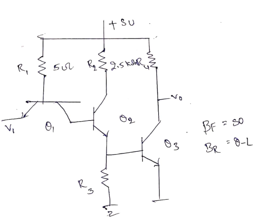
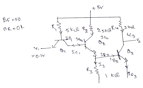
A simplified TTL inverter is show in figure Calculate the power supply currents for Vi=0.1 and Vi=4V.
Vi =0.1V


Vi =4V
 Q1
is in revers active ,Q2 is in saturation and
Q3 is in saturation modes
Q1
is in revers active ,Q2 is in saturation and
Q3 is in saturation modes


Subtitute I3 in equation 1


Add Answer to:
22. A simplified TTL inverter is shown in Figure P4.22. Calculate the power supply currents for...
Figure 3 shows a simplified schematic of a single phase equivalent circuit diagram of inverter coupled...
 Figure 3 shows a simplified schematic of a single phase equivalent circuit diagram of inverter coupled embedded generation, where Vinv is the voltage at the inverter connection point (assume this to be 240VZ0°) Vpcc is the voltage at the point of common coupling Vgnd is the grid voltage X the reactance in the inverter connection (3.6 m) R the resistance in the inverter connection (55 mO) Xgrid is the reactance of the distribution grid (200 m) Rend is the resistance...
Use Kirchhoff's rules to calculate currents I, I1, I2, I3, I4, and I5. One Power Supply...
 Use Kirchhoff's rules to calculate currents I, I1, I2, I3, I4,
and I5.
One Power Supply Multifood Circuit With the power supply unplugged, connect the circuit as shown in Figure 1 with R_1 = 20 ohm, R_2 = 50 ohm, R_3 = 100 ohm, R_4 = 25 ohm, and R_5 = 75 ohm. After the circuit is checked by your instructor, plug in the power supply, turn on the power and adjust the total voltage V to approximately 8.00 V...
Use Kirchhoff's rules to calculate currents I, I1, I2, I3, I4,
and I5.
One Power Supply Multifood Circuit With the power supply unplugged, connect the circuit as shown in Figure 1 with R_1 = 20 ohm, R_2 = 50 ohm, R_3 = 100 ohm, R_4 = 25 ohm, and R_5 = 75 ohm. After the circuit is checked by your instructor, plug in the power supply, turn on the power and adjust the total voltage V to approximately 8.00 V...
The circuit shown below represents two power supply rails of a circuit board fitted with TTL...
 The circuit shown below represents two power supply rails of a circuit board fitted with TTL components (rise time = 10 ns). The DC supply current for each rail is as shown. Measurement of interference on these rails has indicated the presence of capacitive cross-talk. It is observed that 0.75 V, 10 ns rise time transients on the 10 V rail are inducing similar rise time impulses of 150 mV on the 5 V rail. Calculate the value of the...
Question 3 a) Design the resistive load based NMOS inverter in Figure Q3a to provide VOL...
 Question 3 a) Design the resistive load based NMOS inverter in Figure Q3a to provide VOL = 200 mV and to draw a supply current of 80 pA in the low-output state. Let the transistor be specified to have VTN = 0.7 V, KN = 125 JA/V, and I = 0. The power supply VoD = 2.5 V. State any assumptions made. Calculate the required values of W/L and Rp. ii) How much power is drawn from Voo when the...
The class E inverter as shown in Figure 7-1 operates at resonance and has Vs-48 V and R-10 Ω The ...
 The class E inverter as shown in Figure 7-1 operates at resonance and has Vs-48 V and R-10 Ω The switching frequency is fs- 20 kHz. Assume a quality factor Q-7. (a) Calculate the parameters and complete Table 7-1. Assume an ideal transistor switch the optimum values on inductor / the optimum value of capacitor C the optimum values on inductor Le the optimum value of capacitor Ce the damping factor δ the peak output voltage Vo for Vi= 12...
6.28 Consider the simplified electric power system shown in Figure 6.17 for which the power- flow...
 6.28 Consider the simplified electric power system shown in Figure 6.17 for which the power- flow solution can be obtained without resorting to iterative techniques. (a) Compute the elements of the bus admittance matrix Ybus. (b) Calculate the phase angle δ, by using the real power equation at bus 2 (voltage-controlled bus). (c) Determine IV and os by using both the real and reactive power equations at bus 3 (load bus). (d) Find the real power generated at bus 1...
zka or the circuit shown in the figure, a) Calculate the currents in each resistor.--て 12...
 zka or the circuit shown in the figure, a) Calculate the currents in each resistor.--て 12 Calculate the voltage across each resistor. V c) Calculate the power dissipation in each resistor.279 d) Calculate the power output of the battery.How does it compare to your results in part (c) b)
Power electronic Design a Switched Mode Power Supply (SMPS) by following pattern. Finally you should reach a DC outp...
 Power electronic Design a Switched Mode Power Supply (SMPS) by following pattern. Finally you should reach a DC output voltage of 48 V and 20 Ampere. 1. initially start designing an uncontrolled single-phase rectifier supplied by 220 V., 50 Hz grid. A parallel capacitor is connected to the output. Draw its waveform and calculate the average value of the output voltage. Evaluate the input Power-Factor and Crest-Factor problems. (20) a. In order to avoid the input Power-Factor and Crest-Factor problems,...
A common source amplifier circuit based on a single n-channel MOSFET is shown in Figure 4b. Assume that the transconductance gm-60 mS (equivalent to mA/ V) and drain source resistance, os,...
 A common source amplifier circuit based on a single n-channel MOSFET is shown in Figure 4b. Assume that the transconductance gm-60 mS (equivalent to mA/ V) and drain source resistance, os, is so large it may be neglected. 0) Calculate the open circuit voltage gain Av Yout/ Vis. i) The amplifier has a load of 10 k2. Determine the current gain Va. = 12 V 150k 4k3 Vout Vin 200k GND = 0 V Figure 4b a) State the name...
show steps please A2. A simplified car model is shown in Figure A3. It travels horizontally at a constant speed of v 20...
 show steps please
A2. A simplified car model is shown in Figure A3. It travels horizontally at a constant speed of v 20 miles perhour on a bumpy road (1 mile is approximately 1610 meters). The road surface is assumed to be rigid and has a sinusoidal profile. Both masses vibrate only in the vertical direction. m 900kg, m 60kg,k 1,000,000N/m m1 0.5 m 4k 0.1 m Figure A2. [15] [10] (1) Derive the equation of motion for the vertical...
show steps please
A2. A simplified car model is shown in Figure A3. It travels horizontally at a constant speed of v 20 miles perhour on a bumpy road (1 mile is approximately 1610 meters). The road surface is assumed to be rigid and has a sinusoidal profile. Both masses vibrate only in the vertical direction. m 900kg, m 60kg,k 1,000,000N/m m1 0.5 m 4k 0.1 m Figure A2. [15] [10] (1) Derive the equation of motion for the vertical...
 Figure 3 shows a simplified schematic of a single phase equivalent circuit diagram of inverter coupled embedded generation, where Vinv is the voltage at the inverter connection point (assume this to be 240VZ0°) Vpcc is the voltage at the point of common coupling Vgnd is the grid voltage X the reactance in the inverter connection (3.6 m) R the resistance in the inverter connection (55 mO) Xgrid is the reactance of the distribution grid (200 m) Rend is the resistance...
 Use Kirchhoff's rules to calculate currents I, I1, I2, I3, I4,
and I5.
One Power Supply Multifood Circuit With the power supply unplugged, connect the circuit as shown in Figure 1 with R_1 = 20 ohm, R_2 = 50 ohm, R_3 = 100 ohm, R_4 = 25 ohm, and R_5 = 75 ohm. After the circuit is checked by your instructor, plug in the power supply, turn on the power and adjust the total voltage V to approximately 8.00 V...
Use Kirchhoff's rules to calculate currents I, I1, I2, I3, I4,
and I5.
One Power Supply Multifood Circuit With the power supply unplugged, connect the circuit as shown in Figure 1 with R_1 = 20 ohm, R_2 = 50 ohm, R_3 = 100 ohm, R_4 = 25 ohm, and R_5 = 75 ohm. After the circuit is checked by your instructor, plug in the power supply, turn on the power and adjust the total voltage V to approximately 8.00 V...
 The circuit shown below represents two power supply rails of a circuit board fitted with TTL components (rise time = 10 ns). The DC supply current for each rail is as shown. Measurement of interference on these rails has indicated the presence of capacitive cross-talk. It is observed that 0.75 V, 10 ns rise time transients on the 10 V rail are inducing similar rise time impulses of 150 mV on the 5 V rail. Calculate the value of the...
 Question 3 a) Design the resistive load based NMOS inverter in Figure Q3a to provide VOL = 200 mV and to draw a supply current of 80 pA in the low-output state. Let the transistor be specified to have VTN = 0.7 V, KN = 125 JA/V, and I = 0. The power supply VoD = 2.5 V. State any assumptions made. Calculate the required values of W/L and Rp. ii) How much power is drawn from Voo when the...
 The class E inverter as shown in Figure 7-1 operates at resonance and has Vs-48 V and R-10 Ω The switching frequency is fs- 20 kHz. Assume a quality factor Q-7. (a) Calculate the parameters and complete Table 7-1. Assume an ideal transistor switch the optimum values on inductor / the optimum value of capacitor C the optimum values on inductor Le the optimum value of capacitor Ce the damping factor δ the peak output voltage Vo for Vi= 12...
 6.28 Consider the simplified electric power system shown in Figure 6.17 for which the power- flow solution can be obtained without resorting to iterative techniques. (a) Compute the elements of the bus admittance matrix Ybus. (b) Calculate the phase angle δ, by using the real power equation at bus 2 (voltage-controlled bus). (c) Determine IV and os by using both the real and reactive power equations at bus 3 (load bus). (d) Find the real power generated at bus 1...
 zka or the circuit shown in the figure, a) Calculate the currents in each resistor.--て 12 Calculate the voltage across each resistor. V c) Calculate the power dissipation in each resistor.279 d) Calculate the power output of the battery.How does it compare to your results in part (c) b)
 Power electronic Design a Switched Mode Power Supply (SMPS) by following pattern. Finally you should reach a DC output voltage of 48 V and 20 Ampere. 1. initially start designing an uncontrolled single-phase rectifier supplied by 220 V., 50 Hz grid. A parallel capacitor is connected to the output. Draw its waveform and calculate the average value of the output voltage. Evaluate the input Power-Factor and Crest-Factor problems. (20) a. In order to avoid the input Power-Factor and Crest-Factor problems,...
 A common source amplifier circuit based on a single n-channel MOSFET is shown in Figure 4b. Assume that the transconductance gm-60 mS (equivalent to mA/ V) and drain source resistance, os, is so large it may be neglected. 0) Calculate the open circuit voltage gain Av Yout/ Vis. i) The amplifier has a load of 10 k2. Determine the current gain Va. = 12 V 150k 4k3 Vout Vin 200k GND = 0 V Figure 4b a) State the name...
 show steps please
A2. A simplified car model is shown in Figure A3. It travels horizontally at a constant speed of v 20 miles perhour on a bumpy road (1 mile is approximately 1610 meters). The road surface is assumed to be rigid and has a sinusoidal profile. Both masses vibrate only in the vertical direction. m 900kg, m 60kg,k 1,000,000N/m m1 0.5 m 4k 0.1 m Figure A2. [15] [10] (1) Derive the equation of motion for the vertical...
show steps please
A2. A simplified car model is shown in Figure A3. It travels horizontally at a constant speed of v 20 miles perhour on a bumpy road (1 mile is approximately 1610 meters). The road surface is assumed to be rigid and has a sinusoidal profile. Both masses vibrate only in the vertical direction. m 900kg, m 60kg,k 1,000,000N/m m1 0.5 m 4k 0.1 m Figure A2. [15] [10] (1) Derive the equation of motion for the vertical...
Most questions answered within 3 hours.
-
Where is the error in this code sequence?
String s1 = "Hello";
String s2 = "ello";...
asked 10 months ago -
Financial data for Joel de Paris, Inc., for last year
follow:
Joel de Paris, Inc.
Balance...
asked 10 months ago -
Consider this reaction:
Al2(SO4)3 (aq)+ BaCl3
(aq) Al2Cl6 (aq)- +
3BaSO4(s) . What is the...
asked 10 months ago -
Suppose that Savneet is considering increasing her
recent random sample from 20 car rentals to 40...
asked 10 months ago -
Trucks arrive at an unloading terminal at an average rate of 120
per hour.
Trucks arrive...
asked 10 months ago -
Why are methanol and ethanol completely soluble in water while
octanol is not very little soluble....
asked 10 months ago -
A facilities manager at a university reads in a research report
that the mean amount of...
asked 10 months ago -
When the CuSO4 is rehydrated by adding water to the anhydrous
compound, is this an endothermic...
asked 10 months ago -
A ray of sunlight is passing from diamond into crown glass; the
angle of incidence is...
asked 10 months ago -
A block of mass 0.249 kg is placed on top of a light, vertical
spring of...
asked 10 months ago -
how do the kidneys compensate in the presences of acidosis
a) trigger hyperventilate
b) reserve acid...
asked 10 months ago -
Question 501 pts
The rental rate of capital to the firm increases. Which of the
following...
asked 10 months ago