
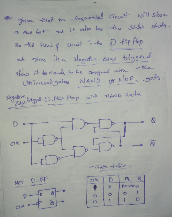
Homework Answers
Here the sequentail circuit with one input and two output stable states with negative edge trigger. The circuit is D Flip Flop
Below is the design and operation of the circuit

Add Answer to:
Hi ... i need answer for this question please
I am waiting your reply ... Thanks?...
how slove 4-34, 4-35, 4-36??? I dont know that! please hlep me! 306 □ CHAPTER 4/SEQUENTIAL CIRCUITS OTABLE 4-16...
 how slove 4-34, 4-35, 4-36??? I dont know that! please hlep me!
306 □ CHAPTER 4/SEQUENTIAL CIRCUITS OTABLE 4-16 State Table for Problem 4-33 Next State Input Output Present State 4-36 4-37 0 0 0 0 4-38 Design the circuit specified by Table 4-14 and use the sequence from Problen 4-31 (either yours or the one posted on the text website) to perform an automatic logic simulation-based verification of your design. 4 433. The state table for a sequential circuit...
how slove 4-34, 4-35, 4-36??? I dont know that! please hlep me!
306 □ CHAPTER 4/SEQUENTIAL CIRCUITS OTABLE 4-16 State Table for Problem 4-33 Next State Input Output Present State 4-36 4-37 0 0 0 0 4-38 Design the circuit specified by Table 4-14 and use the sequence from Problen 4-31 (either yours or the one posted on the text website) to perform an automatic logic simulation-based verification of your design. 4 433. The state table for a sequential circuit...
hi i need answers for nos. 18-28. 1. In a counter, a flip-flop output 10. A...
 hi i need answers for nos. 18-28.
1. In a counter, a flip-flop output 10. A is a group of flip-flops, each one of which transition serves as a source for triggering other flip-flops, not by the common clock pulses. shares a common clock and is capable of storing one bit of information. A) RAM B) latch A ripple Cring (rather than signal transitions) are referred to as B synchronous D binary C) counter D) register 11. The Characteristic Equation...
hi i need answers for nos. 18-28.
1. In a counter, a flip-flop output 10. A is a group of flip-flops, each one of which transition serves as a source for triggering other flip-flops, not by the common clock pulses. shares a common clock and is capable of storing one bit of information. A) RAM B) latch A ripple Cring (rather than signal transitions) are referred to as B synchronous D binary C) counter D) register 11. The Characteristic Equation...
please solve the question completely and show the steps ... thumb up will be given (5 points each) [CO: 6] a. If RO and R1 are both 16-bit serial shift registers, each with a single serial input (S_IN...
 please solve the question completely and show the steps ...
thumb up will be given
(5 points each) [CO: 6] a. If RO and R1 are both 16-bit serial shift registers, each with a single serial input (S_IN) and a single serial output (S_OUT), clock and reset. Design using RO and Rl additional logic, a circuit that would store the output S_OUT of either RO or Rl into a D-FF based on input CH. If CH is 0, S OUT...
please solve the question completely and show the steps ...
thumb up will be given
(5 points each) [CO: 6] a. If RO and R1 are both 16-bit serial shift registers, each with a single serial input (S_IN) and a single serial output (S_OUT), clock and reset. Design using RO and Rl additional logic, a circuit that would store the output S_OUT of either RO or Rl into a D-FF based on input CH. If CH is 0, S OUT...
This was the answer I got, teacher said it was wrong Teacher said, couldnt run the...
 This was the answer I got, teacher said it was wrong
Teacher said, couldnt run the gate because there wasnt any
switches
5. Design and test a simplified logic circuit to identify all numbers in the output range of function: F(x) = 2x+3 for an input domain between 0 and 6. Be sure to include your truth table. Normal 1 No Spac... Heading 1 Head Paragraph Styles t Draw Simulate View Window Help 39 ) ) 11:55 1 esu.desire2learn.com Boolean...
This was the answer I got, teacher said it was wrong
Teacher said, couldnt run the gate because there wasnt any
switches
5. Design and test a simplified logic circuit to identify all numbers in the output range of function: F(x) = 2x+3 for an input domain between 0 and 6. Be sure to include your truth table. Normal 1 No Spac... Heading 1 Head Paragraph Styles t Draw Simulate View Window Help 39 ) ) 11:55 1 esu.desire2learn.com Boolean...
·20) |19) 118) 117) 116) 115) Question 1.(20 points, I point each. Put answers into the...
 ·20) |19) 118) 117) 116) 115) Question 1.(20 points, I point each. Put answers into the above table) 13)一114) 2)- ) S-bit signed binary data can represent the decimal values from 0 to 256 2) 10111 is the two's complement representation of b. False a. True a. -23 b.-9 c.-7 d. +22 e.+7 3) 01110 is the two's complement representation of a.-13 b.-15 c.-9 d.+14 e.+18 a.A. b, B, c.A+B d, B c, (AB). a. Trueb. False a. True a....
Its logic design my sequence is 127605 i need help with all this pages please and thank you
 Its logic design
my sequence is 127605
i need help with all this pages please and thank you
27 60 Experiment 4 Six-State Up-Down Counter 1 Objective To become familiar with the design procedures of a counter, which are applicable to the design of other synchronous sequential circuits. 2 Problem description A six-state up-down counter is to be designed. Three flip-flops with outputs Q2,Qi and Qo are required in the design. As shown in Figure 1, the counter is initialized...
Its logic design
my sequence is 127605
i need help with all this pages please and thank you
27 60 Experiment 4 Six-State Up-Down Counter 1 Objective To become familiar with the design procedures of a counter, which are applicable to the design of other synchronous sequential circuits. 2 Problem description A six-state up-down counter is to be designed. Three flip-flops with outputs Q2,Qi and Qo are required in the design. As shown in Figure 1, the counter is initialized...
 how slove 4-34, 4-35, 4-36??? I dont know that! please hlep me!
306 □ CHAPTER 4/SEQUENTIAL CIRCUITS OTABLE 4-16 State Table for Problem 4-33 Next State Input Output Present State 4-36 4-37 0 0 0 0 4-38 Design the circuit specified by Table 4-14 and use the sequence from Problen 4-31 (either yours or the one posted on the text website) to perform an automatic logic simulation-based verification of your design. 4 433. The state table for a sequential circuit...
how slove 4-34, 4-35, 4-36??? I dont know that! please hlep me!
306 □ CHAPTER 4/SEQUENTIAL CIRCUITS OTABLE 4-16 State Table for Problem 4-33 Next State Input Output Present State 4-36 4-37 0 0 0 0 4-38 Design the circuit specified by Table 4-14 and use the sequence from Problen 4-31 (either yours or the one posted on the text website) to perform an automatic logic simulation-based verification of your design. 4 433. The state table for a sequential circuit...
 hi i need answers for nos. 18-28.
1. In a counter, a flip-flop output 10. A is a group of flip-flops, each one of which transition serves as a source for triggering other flip-flops, not by the common clock pulses. shares a common clock and is capable of storing one bit of information. A) RAM B) latch A ripple Cring (rather than signal transitions) are referred to as B synchronous D binary C) counter D) register 11. The Characteristic Equation...
hi i need answers for nos. 18-28.
1. In a counter, a flip-flop output 10. A is a group of flip-flops, each one of which transition serves as a source for triggering other flip-flops, not by the common clock pulses. shares a common clock and is capable of storing one bit of information. A) RAM B) latch A ripple Cring (rather than signal transitions) are referred to as B synchronous D binary C) counter D) register 11. The Characteristic Equation...
 please solve the question completely and show the steps ...
thumb up will be given
(5 points each) [CO: 6] a. If RO and R1 are both 16-bit serial shift registers, each with a single serial input (S_IN) and a single serial output (S_OUT), clock and reset. Design using RO and Rl additional logic, a circuit that would store the output S_OUT of either RO or Rl into a D-FF based on input CH. If CH is 0, S OUT...
please solve the question completely and show the steps ...
thumb up will be given
(5 points each) [CO: 6] a. If RO and R1 are both 16-bit serial shift registers, each with a single serial input (S_IN) and a single serial output (S_OUT), clock and reset. Design using RO and Rl additional logic, a circuit that would store the output S_OUT of either RO or Rl into a D-FF based on input CH. If CH is 0, S OUT...
 This was the answer I got, teacher said it was wrong
Teacher said, couldnt run the gate because there wasnt any
switches
5. Design and test a simplified logic circuit to identify all numbers in the output range of function: F(x) = 2x+3 for an input domain between 0 and 6. Be sure to include your truth table. Normal 1 No Spac... Heading 1 Head Paragraph Styles t Draw Simulate View Window Help 39 ) ) 11:55 1 esu.desire2learn.com Boolean...
This was the answer I got, teacher said it was wrong
Teacher said, couldnt run the gate because there wasnt any
switches
5. Design and test a simplified logic circuit to identify all numbers in the output range of function: F(x) = 2x+3 for an input domain between 0 and 6. Be sure to include your truth table. Normal 1 No Spac... Heading 1 Head Paragraph Styles t Draw Simulate View Window Help 39 ) ) 11:55 1 esu.desire2learn.com Boolean...
 ·20) |19) 118) 117) 116) 115) Question 1.(20 points, I point each. Put answers into the above table) 13)一114) 2)- ) S-bit signed binary data can represent the decimal values from 0 to 256 2) 10111 is the two's complement representation of b. False a. True a. -23 b.-9 c.-7 d. +22 e.+7 3) 01110 is the two's complement representation of a.-13 b.-15 c.-9 d.+14 e.+18 a.A. b, B, c.A+B d, B c, (AB). a. Trueb. False a. True a....
 Its logic design
my sequence is 127605
i need help with all this pages please and thank you
27 60 Experiment 4 Six-State Up-Down Counter 1 Objective To become familiar with the design procedures of a counter, which are applicable to the design of other synchronous sequential circuits. 2 Problem description A six-state up-down counter is to be designed. Three flip-flops with outputs Q2,Qi and Qo are required in the design. As shown in Figure 1, the counter is initialized...
Its logic design
my sequence is 127605
i need help with all this pages please and thank you
27 60 Experiment 4 Six-State Up-Down Counter 1 Objective To become familiar with the design procedures of a counter, which are applicable to the design of other synchronous sequential circuits. 2 Problem description A six-state up-down counter is to be designed. Three flip-flops with outputs Q2,Qi and Qo are required in the design. As shown in Figure 1, the counter is initialized...
Most questions answered within 3 hours.
-
Where is the error in this code sequence?
String s1 = "Hello";
String s2 = "ello";...
asked 10 months ago -
Financial data for Joel de Paris, Inc., for last year
follow:
Joel de Paris, Inc.
Balance...
asked 10 months ago -
Consider this reaction:
Al2(SO4)3 (aq)+ BaCl3
(aq) Al2Cl6 (aq)- +
3BaSO4(s) . What is the...
asked 10 months ago -
Suppose that Savneet is considering increasing her
recent random sample from 20 car rentals to 40...
asked 10 months ago -
Trucks arrive at an unloading terminal at an average rate of 120
per hour.
Trucks arrive...
asked 10 months ago -
Why are methanol and ethanol completely soluble in water while
octanol is not very little soluble....
asked 10 months ago -
A facilities manager at a university reads in a research report
that the mean amount of...
asked 10 months ago -
When the CuSO4 is rehydrated by adding water to the anhydrous
compound, is this an endothermic...
asked 10 months ago -
A ray of sunlight is passing from diamond into crown glass; the
angle of incidence is...
asked 10 months ago -
A block of mass 0.249 kg is placed on top of a light, vertical
spring of...
asked 10 months ago -
how do the kidneys compensate in the presences of acidosis
a) trigger hyperventilate
b) reserve acid...
asked 10 months ago -
Question 501 pts
The rental rate of capital to the firm increases. Which of the
following...
asked 10 months ago