In order to change the colors of an RGB LED using a MSP430 Microcontroller with a...
In order to change the colors of an RGB LED using a MSP430 Microcontroller with a potentiometer (analog) and 3 push buttons, what settings in the assembly code do we need to have for the ADC12 converter, the compare mode and timerA0?
Homework Answers
Request Answer!
We need at least 10 more requests to produce the answer.
0 / 10 have requested this problem solution
The more requests, the faster the answer.
Add Answer to:
In order to change the colors of an RGB LED using a MSP430
Microcontroller with a...
simple MSP430 Q&A QUESTION run on Code Composer Studio flashing led 1. In this lab, we...
simple MSP430 Q&A QUESTION run on Code Composer Studio flashing led 1. In this lab, we used a delay loop to create a small delay; what is its effect on the battery life if the device is battery operated? Is it a good way of generating delays? 2. The MSP430 CPU runs on a clock that can be slowed down or sped up; what happens to the delay generated by the delay loop if the clock driving the CPU speeds...
It's an Energia sketch using C language. We work with MSP430 Launchpad but you shouldn't need...
 It's an Energia sketch using C language. We
work with MSP430 Launchpad but you shouldn't need it to write the
code.
I'm really stuck :(
Problem 2 (50 points) One common method of outputting an "effective" analog signal is to use pulse width modulation or PWM. In this modulation scheme, a high frequency square wave is switched on and off with a duty cycle determined by the desired output intensity, where Duty Cycle = Time spend "on" Total period 50%...
It's an Energia sketch using C language. We
work with MSP430 Launchpad but you shouldn't need it to write the
code.
I'm really stuck :(
Problem 2 (50 points) One common method of outputting an "effective" analog signal is to use pulse width modulation or PWM. In this modulation scheme, a high frequency square wave is switched on and off with a duty cycle determined by the desired output intensity, where Duty Cycle = Time spend "on" Total period 50%...
ANSWER THE QUESTION IN THE END READING THE DIAL WITH THE AVR ATMEGA16 MICROCONTROLLER #include <axc/ie.h>...
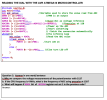 ANSWER THE QUESTION IN THE END
READING THE DIAL WITH THE AVR ATMEGA16 MICROCONTROLLER #include <axc/ie.h> int main(void) int ads.valusimm 1/Variable used to store the value read from ADC DDRB = (1<<PBC); //PB® is an output ADMUX = (1<<REFSO); ADMUX &= -(1<<REFS1mm //Axcs(+5v) as voltage reference ADCSRA != ((1<<ADPS2) (1<<ADP51)|(1<<ADPS0)); //ecessalec at 128 ADCSRA |= (1<<ADEN); 1/Power up the ADC ADCSRA - (1<<ADSC); 1/Start converting ADCSRA |= (1<<ADATE); // finish the conversion automatically while(1) { //The infinite loop adc value...
ANSWER THE QUESTION IN THE END
READING THE DIAL WITH THE AVR ATMEGA16 MICROCONTROLLER #include <axc/ie.h> int main(void) int ads.valusimm 1/Variable used to store the value read from ADC DDRB = (1<<PBC); //PB® is an output ADMUX = (1<<REFSO); ADMUX &= -(1<<REFS1mm //Axcs(+5v) as voltage reference ADCSRA != ((1<<ADPS2) (1<<ADP51)|(1<<ADPS0)); //ecessalec at 128 ADCSRA |= (1<<ADEN); 1/Power up the ADC ADCSRA - (1<<ADSC); 1/Start converting ADCSRA |= (1<<ADATE); // finish the conversion automatically while(1) { //The infinite loop adc value...
in MSP430 design tutorial using F5529 in lab 6 If I wanted to blink LED2 (green)...
in MSP430 design tutorial using F5529 in lab 6 If I wanted to blink LED2 (green) every 2 seconds and LED1 (red) every 1 seconds, how would I set it up using Timers and Interrupts? You need not write any code, just explain how you would do it. (Hint: I’m not looking for a long answer here, but you’d have to do something different than what you did in lab).
1. How many Timers does the F5529 have? Name them. What happens when the Timer overflows?...
 1. How many Timers does the F5529 have? Name them. What happens when the Timer overflows? And what exactly does "overflow" mean? 2. What is the name of the register that "counts?" 3. 4. What is the name of the Timer A Interrupt Flag? 5. What is "resolution?" State 2 ways you can change it. What are the different Timer Modes and how do they work? 6. 7. What is the advantage of Up Mode vs Continuous Mode? What settings...
I need help with doing these tasks for code composer Lab 3 - Branching, Push Button...
 I need help with doing these tasks for code
composer
Lab 3 - Branching, Push Button and LEDs-Reading Assignment in this lab, we are going to control a LED via a push button- using general purpose digital 10 for both input (button) and output (LED) on port 1 - using Code Composer Studio. Furthermore, we are going to use a branch instruction to create an IF-ELSE structure in assembly to determine if the LED should be lit up based on...
I need help with doing these tasks for code
composer
Lab 3 - Branching, Push Button and LEDs-Reading Assignment in this lab, we are going to control a LED via a push button- using general purpose digital 10 for both input (button) and output (LED) on port 1 - using Code Composer Studio. Furthermore, we are going to use a branch instruction to create an IF-ELSE structure in assembly to determine if the LED should be lit up based on...
Task The task for this assignment is to have the following user-defined data type: struct rgb...
Task The task for this assignment is to have the following user-defined data type: struct rgb { unsigned char red; unsigned char green; unsigned char blue; }; be able to be: read in from a stream (e.g., std::cin), i.e., write: std::istream& operator >>(std::istream& is, rgb& colour); (see below) written out to a stream (e.g., std::cout), i.e., write: std::ostream& operator <<(std::ostream& os, rgb const& colour); (see below) stored in a container, e.g., std::vector<rgb>, std::array<rgb,16>; (see below) processed via algorithms (and other...
help me, how can wright the code using ( atmel 7 ) ( GCC C ASF Board Project ) C/C++ Equipment and Materials SAMD21 or...
 help me, how can wright the code using ( atmel 7 )
( GCC C ASF Board Project ) C/C++
Equipment and Materials SAMD21 or SAMW25 Xplained Pro 1) 2) USB cable 3) PC ELVIS II board 4) Program UART Write a program that uses the default UART interface of the SAMD21 microcontroller to communicate with over the the UART of the EDBG microcontroller. The EDBG chip will then convert the serial data and send this USB to the PC....
help me, how can wright the code using ( atmel 7 )
( GCC C ASF Board Project ) C/C++
Equipment and Materials SAMD21 or SAMW25 Xplained Pro 1) 2) USB cable 3) PC ELVIS II board 4) Program UART Write a program that uses the default UART interface of the SAMD21 microcontroller to communicate with over the the UART of the EDBG microcontroller. The EDBG chip will then convert the serial data and send this USB to the PC....
help me, how can wright the code using ( atmel 7 ) ( GCC C ASF Board Project ) C/C++ Equipment and Materials SAMD21 or...
 help me, how can wright the code using ( atmel 7 )
( GCC C ASF Board Project ) C/C++
Equipment and Materials SAMD21 or SAMW25 Xplained Pro 1) 2) USB cable 3) PC ELVIS II board 4) Program UART Write a program that uses the default UART interface of the SAMD21 microcontroller to communicate with over the the UART of the EDBG microcontroller. The EDBG chip will then convert the serial data and send this USB to the PC....
help me, how can wright the code using ( atmel 7 )
( GCC C ASF Board Project ) C/C++
Equipment and Materials SAMD21 or SAMW25 Xplained Pro 1) 2) USB cable 3) PC ELVIS II board 4) Program UART Write a program that uses the default UART interface of the SAMD21 microcontroller to communicate with over the the UART of the EDBG microcontroller. The EDBG chip will then convert the serial data and send this USB to the PC....
help me, how can wright the code using ( atmel 7 ) ( GCC C ASF Board Project ) C/C++ Equipment and Materials SAMD21 or...
 help me, how can wright the code using ( atmel 7 )
( GCC C ASF Board Project ) C/C++
Equipment and Materials SAMD21 or SAMW25 Xplained Pro 1) 2) USB cable 3) PC ELVIS II board 4) Program UART Write a program that uses the default UART interface of the SAMD21 microcontroller to communicate with over the the UART of the EDBG microcontroller. The EDBG chip will then convert the serial data and send this USB to the PC....
help me, how can wright the code using ( atmel 7 )
( GCC C ASF Board Project ) C/C++
Equipment and Materials SAMD21 or SAMW25 Xplained Pro 1) 2) USB cable 3) PC ELVIS II board 4) Program UART Write a program that uses the default UART interface of the SAMD21 microcontroller to communicate with over the the UART of the EDBG microcontroller. The EDBG chip will then convert the serial data and send this USB to the PC....
 It's an Energia sketch using C language. We
work with MSP430 Launchpad but you shouldn't need it to write the
code.
I'm really stuck :(
Problem 2 (50 points) One common method of outputting an "effective" analog signal is to use pulse width modulation or PWM. In this modulation scheme, a high frequency square wave is switched on and off with a duty cycle determined by the desired output intensity, where Duty Cycle = Time spend "on" Total period 50%...
It's an Energia sketch using C language. We
work with MSP430 Launchpad but you shouldn't need it to write the
code.
I'm really stuck :(
Problem 2 (50 points) One common method of outputting an "effective" analog signal is to use pulse width modulation or PWM. In this modulation scheme, a high frequency square wave is switched on and off with a duty cycle determined by the desired output intensity, where Duty Cycle = Time spend "on" Total period 50%...
 ANSWER THE QUESTION IN THE END
READING THE DIAL WITH THE AVR ATMEGA16 MICROCONTROLLER #include <axc/ie.h> int main(void) int ads.valusimm 1/Variable used to store the value read from ADC DDRB = (1<<PBC); //PB® is an output ADMUX = (1<<REFSO); ADMUX &= -(1<<REFS1mm //Axcs(+5v) as voltage reference ADCSRA != ((1<<ADPS2) (1<<ADP51)|(1<<ADPS0)); //ecessalec at 128 ADCSRA |= (1<<ADEN); 1/Power up the ADC ADCSRA - (1<<ADSC); 1/Start converting ADCSRA |= (1<<ADATE); // finish the conversion automatically while(1) { //The infinite loop adc value...
ANSWER THE QUESTION IN THE END
READING THE DIAL WITH THE AVR ATMEGA16 MICROCONTROLLER #include <axc/ie.h> int main(void) int ads.valusimm 1/Variable used to store the value read from ADC DDRB = (1<<PBC); //PB® is an output ADMUX = (1<<REFSO); ADMUX &= -(1<<REFS1mm //Axcs(+5v) as voltage reference ADCSRA != ((1<<ADPS2) (1<<ADP51)|(1<<ADPS0)); //ecessalec at 128 ADCSRA |= (1<<ADEN); 1/Power up the ADC ADCSRA - (1<<ADSC); 1/Start converting ADCSRA |= (1<<ADATE); // finish the conversion automatically while(1) { //The infinite loop adc value...
 1. How many Timers does the F5529 have? Name them. What happens when the Timer overflows? And what exactly does "overflow" mean? 2. What is the name of the register that "counts?" 3. 4. What is the name of the Timer A Interrupt Flag? 5. What is "resolution?" State 2 ways you can change it. What are the different Timer Modes and how do they work? 6. 7. What is the advantage of Up Mode vs Continuous Mode? What settings...
 I need help with doing these tasks for code
composer
Lab 3 - Branching, Push Button and LEDs-Reading Assignment in this lab, we are going to control a LED via a push button- using general purpose digital 10 for both input (button) and output (LED) on port 1 - using Code Composer Studio. Furthermore, we are going to use a branch instruction to create an IF-ELSE structure in assembly to determine if the LED should be lit up based on...
I need help with doing these tasks for code
composer
Lab 3 - Branching, Push Button and LEDs-Reading Assignment in this lab, we are going to control a LED via a push button- using general purpose digital 10 for both input (button) and output (LED) on port 1 - using Code Composer Studio. Furthermore, we are going to use a branch instruction to create an IF-ELSE structure in assembly to determine if the LED should be lit up based on...
 help me, how can wright the code using ( atmel 7 )
( GCC C ASF Board Project ) C/C++
Equipment and Materials SAMD21 or SAMW25 Xplained Pro 1) 2) USB cable 3) PC ELVIS II board 4) Program UART Write a program that uses the default UART interface of the SAMD21 microcontroller to communicate with over the the UART of the EDBG microcontroller. The EDBG chip will then convert the serial data and send this USB to the PC....
help me, how can wright the code using ( atmel 7 )
( GCC C ASF Board Project ) C/C++
Equipment and Materials SAMD21 or SAMW25 Xplained Pro 1) 2) USB cable 3) PC ELVIS II board 4) Program UART Write a program that uses the default UART interface of the SAMD21 microcontroller to communicate with over the the UART of the EDBG microcontroller. The EDBG chip will then convert the serial data and send this USB to the PC....
 help me, how can wright the code using ( atmel 7 )
( GCC C ASF Board Project ) C/C++
Equipment and Materials SAMD21 or SAMW25 Xplained Pro 1) 2) USB cable 3) PC ELVIS II board 4) Program UART Write a program that uses the default UART interface of the SAMD21 microcontroller to communicate with over the the UART of the EDBG microcontroller. The EDBG chip will then convert the serial data and send this USB to the PC....
help me, how can wright the code using ( atmel 7 )
( GCC C ASF Board Project ) C/C++
Equipment and Materials SAMD21 or SAMW25 Xplained Pro 1) 2) USB cable 3) PC ELVIS II board 4) Program UART Write a program that uses the default UART interface of the SAMD21 microcontroller to communicate with over the the UART of the EDBG microcontroller. The EDBG chip will then convert the serial data and send this USB to the PC....
 help me, how can wright the code using ( atmel 7 )
( GCC C ASF Board Project ) C/C++
Equipment and Materials SAMD21 or SAMW25 Xplained Pro 1) 2) USB cable 3) PC ELVIS II board 4) Program UART Write a program that uses the default UART interface of the SAMD21 microcontroller to communicate with over the the UART of the EDBG microcontroller. The EDBG chip will then convert the serial data and send this USB to the PC....
help me, how can wright the code using ( atmel 7 )
( GCC C ASF Board Project ) C/C++
Equipment and Materials SAMD21 or SAMW25 Xplained Pro 1) 2) USB cable 3) PC ELVIS II board 4) Program UART Write a program that uses the default UART interface of the SAMD21 microcontroller to communicate with over the the UART of the EDBG microcontroller. The EDBG chip will then convert the serial data and send this USB to the PC....
Most questions answered within 3 hours.
-
Where is the error in this code sequence?
String s1 = "Hello";
String s2 = "ello";...
asked 11 months ago -
Financial data for Joel de Paris, Inc., for last year
follow:
Joel de Paris, Inc.
Balance...
asked 11 months ago -
Consider this reaction:
Al2(SO4)3 (aq)+ BaCl3
(aq) Al2Cl6 (aq)- +
3BaSO4(s) . What is the...
asked 11 months ago -
Suppose that Savneet is considering increasing her
recent random sample from 20 car rentals to 40...
asked 11 months ago -
Trucks arrive at an unloading terminal at an average rate of 120
per hour.
Trucks arrive...
asked 11 months ago -
Why are methanol and ethanol completely soluble in water while
octanol is not very little soluble....
asked 11 months ago -
A facilities manager at a university reads in a research report
that the mean amount of...
asked 11 months ago -
When the CuSO4 is rehydrated by adding water to the anhydrous
compound, is this an endothermic...
asked 11 months ago -
A ray of sunlight is passing from diamond into crown glass; the
angle of incidence is...
asked 11 months ago -
A block of mass 0.249 kg is placed on top of a light, vertical
spring of...
asked 11 months ago -
how do the kidneys compensate in the presences of acidosis
a) trigger hyperventilate
b) reserve acid...
asked 11 months ago -
Question 501 pts
The rental rate of capital to the firm increases. Which of the
following...
asked 11 months ago