If the ferquency of 6 bit counter is 10 MHz, then estimate the frequency for output...
If the ferquency of 6 bit counter is 10 MHz, then estimate the frequency for output bit?
1- Bit-0
2- Bit-1
3- bit-2
4- Bit-3
5- Bit-4
6- Bit-5
Homework Answers
Request Answer!
We need at least 10 more requests to produce the answer.
0 / 10 have requested this problem solution
The more requests, the faster the answer.
Add Answer to:
If the ferquency of 6 bit counter is 10 MHz, then estimate the
frequency for output...
1,A MOD 12 and a MOD 10 counter are cascaded. The input clock frequency is 60 MHz. Determine the ...
1,A MOD 12 and a MOD 10 counter are cascaded. The input clock frequency is 60 MHz. Determine the counter output frequency. 2.What is the output state of a MOD-64 counter after 92 input pulses if the starting state is 000000? 3.What is the frequency factor of a mod 16 counter? 4. How many flip flops are required to design a mod 16 counter? 5. In a mod 10 counter we can distinguish _ different states.
(3 points) The clock on the Basys-3 board is 100 MHz, so it has a 10...
 (3 points) The clock on the Basys-3 board is 100 MHz, so it has a 10 ns period (the time from the rising edge of one clock cycle to the next is 10 ns). For a 3-bit counter there are 8 clock cycles from the rising edge of one roll signal to the next. Therefore, the period of the roll signal is 80 ns and the frequency is 12.5 MHz. Complete the following table for various sizes of counters. Be...
What input clock frequency is required to have a 4-bit counter generate an output of 1Khz...
What input clock frequency is required to have a 4-bit counter generate an output of 1Khz on its MSB?
Module 72: Using this 4 Do bit up-counter, draw the Di diagram for a modulo counter...
 Module 72: Using this 4 Do bit up-counter, draw the Di diagram for a modulo counter which starts at 2 and counts up to 10, Load i.е., 2, 3, 4, 5, 6, 7, 8, 9, 10, 2, 3 0 D2 D3 Q2 Q3 Enable
Design 5 seconds. Use 8-bit counter and logic gates for your hardware design Assume clock frequency...
 Design 5 seconds. Use 8-bit counter and logic gates for your hardware design Assume clock frequency of 80 Hz for the 8-bit counters that are used in the design Show all work and provide the logic diagram for full credit Watchdog-Timer that will generate an overflow (interrupt) output every a
Design 5 seconds. Use 8-bit counter and logic gates for your hardware design Assume clock frequency of 80 Hz for the 8-bit counters that are used in the design Show...
Design 5 seconds. Use 8-bit counter and logic gates for your hardware design Assume clock frequency of 80 Hz for the 8-bit counters that are used in the design Show all work and provide the logic diagram for full credit Watchdog-Timer that will generate an overflow (interrupt) output every a
Design 5 seconds. Use 8-bit counter and logic gates for your hardware design Assume clock frequency of 80 Hz for the 8-bit counters that are used in the design Show...
Consider the circuit in Figure 1. It is a 4-bit (QQ2Q3) synchronous counter which uses four T-typ...
 Consider the circuit in Figure 1. It is a 4-bit (QQ2Q3) synchronous counter which uses four T-type flip-flops. The counter increases its value on each positive edge of the clock if the Enable signal is asserted. The counter is reset to 0 by setting the Clear signal low. You are to implement an 8-bit counter of this type Enable T Q Clock Clear Figure 1. 4-bit synchronous counter (but you need to implement 8-bit counter in this lab) Specific notes:...
3-bit synchronous counter
Design a 3-bit synchronous counter that counts the sequence 7, 4, 2, 1, 6, 5, 7, ect. Use "don't-cares" for the "next states" of the unwanted states. Use a D flip flopfor the most significant bit, a T flip flop for the middle bit, and a JK flip flop for the least significant bit. Use SOP.
The clock rate of a counter is fo = 10 MHz, its relative error is ho = 10 ppm. The capacity of th...
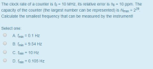 The clock rate of a counter is fo = 10 MHz, its relative error is ho = 10 ppm. The capacity of the counter (the largest number can be represented) is Nmax 220 Calculate the smallest frequency that can be measured by the instrument! Select one: OA. min 0.1 Hz B min 9.54 Hz C.fmin = 10 Hz D.in 0.105 Hz O
The clock rate of a counter is fo = 10 MHz, its relative error is ho = 10...
The clock rate of a counter is fo = 10 MHz, its relative error is ho = 10 ppm. The capacity of the counter (the largest number can be represented) is Nmax 220 Calculate the smallest frequency that can be measured by the instrument! Select one: OA. min 0.1 Hz B min 9.54 Hz C.fmin = 10 Hz D.in 0.105 Hz O
The clock rate of a counter is fo = 10 MHz, its relative error is ho = 10...
Finite state machine (FSM) counter design: Gray codes have a useful property in that consecutive numbers differ in only a single bit position. Table 1 lists a 3-bit modulo 8 Gray code representing the...
 Finite state machine (FSM) counter design: Gray
codes have a useful property in that consecutive numbers differ in
only a single bit position. Table 1 lists a 3-bit modulo 8 Gray
code representing the numbers 0 to 7. Design a 3-bit modulo 8 Gray
code counter FSM.
a) First design and sketch a 3-bit modulo 8 Gray code counter
FSM with no inputs and three outputs, the 3-bit signal
Q2:0. (A modulo N counter counts from 0 to N −...
Finite state machine (FSM) counter design: Gray
codes have a useful property in that consecutive numbers differ in
only a single bit position. Table 1 lists a 3-bit modulo 8 Gray
code representing the numbers 0 to 7. Design a 3-bit modulo 8 Gray
code counter FSM.
a) First design and sketch a 3-bit modulo 8 Gray code counter
FSM with no inputs and three outputs, the 3-bit signal
Q2:0. (A modulo N counter counts from 0 to N −...
Problem 4 [40 Points]: Finite State Machines Show the FSM diagram of a 3-bit up/down counter...
 Problem 4 [40 Points]: Finite State Machines Show the FSM diagram of a 3-bit up/down counter that counts through the sequence 0, 1, 2, 3, 4, 5, 6, 7, 0, 1,2, The counter has two input signals a co up and a count down. Thus, the counter can with a change of input count 5, 4, 3,
 (3 points) The clock on the Basys-3 board is 100 MHz, so it has a 10 ns period (the time from the rising edge of one clock cycle to the next is 10 ns). For a 3-bit counter there are 8 clock cycles from the rising edge of one roll signal to the next. Therefore, the period of the roll signal is 80 ns and the frequency is 12.5 MHz. Complete the following table for various sizes of counters. Be...
 Module 72: Using this 4 Do bit up-counter, draw the Di diagram for a modulo counter which starts at 2 and counts up to 10, Load i.е., 2, 3, 4, 5, 6, 7, 8, 9, 10, 2, 3 0 D2 D3 Q2 Q3 Enable
 Design 5 seconds. Use 8-bit counter and logic gates for your hardware design Assume clock frequency of 80 Hz for the 8-bit counters that are used in the design Show all work and provide the logic diagram for full credit Watchdog-Timer that will generate an overflow (interrupt) output every a
Design 5 seconds. Use 8-bit counter and logic gates for your hardware design Assume clock frequency of 80 Hz for the 8-bit counters that are used in the design Show...
Design 5 seconds. Use 8-bit counter and logic gates for your hardware design Assume clock frequency of 80 Hz for the 8-bit counters that are used in the design Show all work and provide the logic diagram for full credit Watchdog-Timer that will generate an overflow (interrupt) output every a
Design 5 seconds. Use 8-bit counter and logic gates for your hardware design Assume clock frequency of 80 Hz for the 8-bit counters that are used in the design Show...
 Consider the circuit in Figure 1. It is a 4-bit (QQ2Q3) synchronous counter which uses four T-type flip-flops. The counter increases its value on each positive edge of the clock if the Enable signal is asserted. The counter is reset to 0 by setting the Clear signal low. You are to implement an 8-bit counter of this type Enable T Q Clock Clear Figure 1. 4-bit synchronous counter (but you need to implement 8-bit counter in this lab) Specific notes:...
 The clock rate of a counter is fo = 10 MHz, its relative error is ho = 10 ppm. The capacity of the counter (the largest number can be represented) is Nmax 220 Calculate the smallest frequency that can be measured by the instrument! Select one: OA. min 0.1 Hz B min 9.54 Hz C.fmin = 10 Hz D.in 0.105 Hz O
The clock rate of a counter is fo = 10 MHz, its relative error is ho = 10...
The clock rate of a counter is fo = 10 MHz, its relative error is ho = 10 ppm. The capacity of the counter (the largest number can be represented) is Nmax 220 Calculate the smallest frequency that can be measured by the instrument! Select one: OA. min 0.1 Hz B min 9.54 Hz C.fmin = 10 Hz D.in 0.105 Hz O
The clock rate of a counter is fo = 10 MHz, its relative error is ho = 10...
 Finite state machine (FSM) counter design: Gray
codes have a useful property in that consecutive numbers differ in
only a single bit position. Table 1 lists a 3-bit modulo 8 Gray
code representing the numbers 0 to 7. Design a 3-bit modulo 8 Gray
code counter FSM.
a) First design and sketch a 3-bit modulo 8 Gray code counter
FSM with no inputs and three outputs, the 3-bit signal
Q2:0. (A modulo N counter counts from 0 to N −...
Finite state machine (FSM) counter design: Gray
codes have a useful property in that consecutive numbers differ in
only a single bit position. Table 1 lists a 3-bit modulo 8 Gray
code representing the numbers 0 to 7. Design a 3-bit modulo 8 Gray
code counter FSM.
a) First design and sketch a 3-bit modulo 8 Gray code counter
FSM with no inputs and three outputs, the 3-bit signal
Q2:0. (A modulo N counter counts from 0 to N −...
 Problem 4 [40 Points]: Finite State Machines Show the FSM diagram of a 3-bit up/down counter that counts through the sequence 0, 1, 2, 3, 4, 5, 6, 7, 0, 1,2, The counter has two input signals a co up and a count down. Thus, the counter can with a change of input count 5, 4, 3,
Most questions answered within 3 hours.
-
Where is the error in this code sequence?
String s1 = "Hello";
String s2 = "ello";...
asked 11 months ago -
Financial data for Joel de Paris, Inc., for last year
follow:
Joel de Paris, Inc.
Balance...
asked 11 months ago -
Consider this reaction:
Al2(SO4)3 (aq)+ BaCl3
(aq) Al2Cl6 (aq)- +
3BaSO4(s) . What is the...
asked 11 months ago -
Suppose that Savneet is considering increasing her
recent random sample from 20 car rentals to 40...
asked 11 months ago -
Trucks arrive at an unloading terminal at an average rate of 120
per hour.
Trucks arrive...
asked 11 months ago -
Why are methanol and ethanol completely soluble in water while
octanol is not very little soluble....
asked 11 months ago -
A facilities manager at a university reads in a research report
that the mean amount of...
asked 11 months ago -
When the CuSO4 is rehydrated by adding water to the anhydrous
compound, is this an endothermic...
asked 11 months ago -
A ray of sunlight is passing from diamond into crown glass; the
angle of incidence is...
asked 11 months ago -
A block of mass 0.249 kg is placed on top of a light, vertical
spring of...
asked 11 months ago -
how do the kidneys compensate in the presences of acidosis
a) trigger hyperventilate
b) reserve acid...
asked 11 months ago -
Question 501 pts
The rental rate of capital to the firm increases. Which of the
following...
asked 11 months ago