Describe the entity-relationship model. How are entities, relationships, and attributes represented in this model?What is a...
Describe the entity-relationship model. How are entities,
relationships, and attributes represented in this model?What is a
composite entity? Describe the approach to diagrams that use a
crow's foot. Describe how you wouldrepresent cardinality in an E-R
diagram.
Homework Answers
ER Model is an abbreviation for Entity-Relationship Model. A mere full-form of the term explains to us that the ER Model is some kind of a diagram that is going to show us the Relationships established between Entities. An Entity-Relationship Model is resourceful in designing the logical view of any system from a Designer's or a Modeler's perspective. Usually, this Model diagram-illustration is used in systems where the Object-Oriented Programming via the OOPS Methodology is utilized.
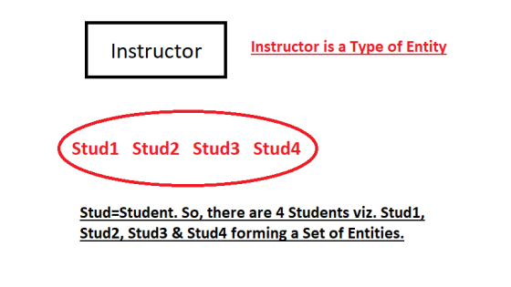
What kind of Entities? Entities in Computer systems represent the Real-world objects and those objects have certain relationships among them which are represented by varied kinds of Relationships in the Computer system. Entities are objects with any kind of physical existence or conceptual existence. Example: person, vehicle, estate, enterprise, tasks or academic program. Entity Type is the object and Entity Set is the collection-group of all entities Example is as illustrated in the diagram below.
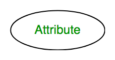
A. Attribute: The characteristics of the Entities that describe the properties of the specific entity are called as Attributes of the Entity. Example: Employee_ID, Emp_Name, DOB, Age, Address, Mobile_No, Emp_Salary, etc. are the attributes that describe the Entity Type Employee. The Attribute is represented by a Horizontal Oval in any ER diagram.
Types of Attributes as follows:
1. Key Attribute: Uniquely identifies each and every entity in the list of entity sets. Example: Roll_No is unique to every Student. The key attribute is represented by an oval with underlying lines.

2. Composite Attribute: Composite attribute is always composed of many different attributes. Example: Attribute Address of Entity type Student comprises of Street, City, State, and Country. Composite Attribute is represented by an oval comprising of many other ovals.

3. Multivalued Attribute: Consists of more than one value for a specific entity. Example: Phone_No (can be more than one for a given student). Any Multivalued Attribute is represented by a double oval.

4. Derived Attribute: Derived Attributes are derived from other attributes Example: Age (can be derived from Date-Of-Birth). Derived Attribute is represented by a dashed oval.

The complete entity type Student with its attributes can be represented as:

Relationship Type: The kind of association among the same or different kinds of entities is the Entity-Relationship Type. Example: A relationship type ‘Enrolled in’ exists between entities Student and Course. A Relationship Type, in the ER model, is represented as a Diamond that is connecting the entities with lines.

Relationship Set: A Set of similar types of relationships. Example: S, E, and C are different Entity Sets (comprising various Entities within) where S1 is enrolled in C2, S2 is enrolled in C1 and S3 is enrolled in C3.
Relationship Set Degree: Number/amount of Entity Sets participating in a relationship set.
- Unary Relationship: The relationship is called
a Unary relationship when Only ONE entity set is
participating in a relation. Example: One Person is Married to Only
One other Person.

- Binary Relationship: The relationship is
called a Binary relationship if there are Two Entities'
set participating in a relation. Example: A Student is enrolled in
a Course.

- n-ary Relationship: n number of Entities' set participating in a relation is called an n-ary relationship.


Cardinality in an ER Diagram: Cardinality of any relationship in the ER Model can be defined as the number of times relationship set's entity from an entity set participates.
Types of Cardinality:
- One-to-one: When each entity in each entity
set can take part only once in the relationship, the cardinality is
one-to-one. Example: One Male can Marry to One Female and One
Female can Marry One Male. So the relationship will be one-to-one.

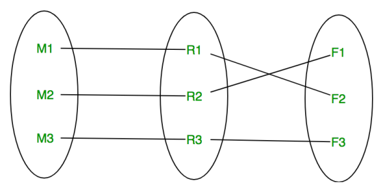
Using Entities' Sets, One-to-One Relationship is represented as:
(M==Male; F==Female; R==Relationship)
- Many-to-one: When entities in one entity set
can take part only once in the relationship set and entities in
other entity sets can take part more than once in the relationship
set, their Cardinality is many-to-one. Example: One Student takes
Only One Course but One Course can be taken by Many Students. The
Cardinality here is n-to-1. This
means, for 1 Course there can be n number of
Students but for One Student, there will be Only One Course.

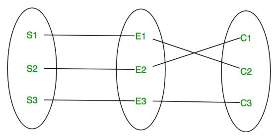
Using Entities' Sets, it is represented as:
(S==Student; C==Course; R==Relationship)
In this case, each student is taking only 1 course but 1 course has been taken by many students.
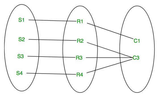
- Many-to-many: When entities in all entity sets
can take part more than once in the relationship, the Cardinality
is many-to-many. Example: One Student can take more than One Course
and one course can be taken by Many Students. So, the relationship
will be many-to-many.

Using Entities' Sets, it is represented as:
(S==Student; C==Course; R==Relationship)


In this example, student S1 is enrolled in C1 and C3 and Course C3 is enrolled by S1, S3, and S4. So it is many-to-many relationships.
Crow's Foot: (Due to Shortage of Time, I am not including a detailed explanation here)
Crow's Foot notation facilitates the relationships to not have any Attribute. When the Crow's Foot notation is implemented, the relationships are elevated or promoted to entities and entity sets. Example: if it is necessary to record where and when any Employee worked and performed any specific task excellently, a new entity "performance" is created and attributed reflecting with the timestamp as well as the location, company_name, and the relationship-association of the employee to the specific job-task becomes an indirect association relationship via the performance (employee-works-performance, performance-facilitates-job).
The symbols used to represent Cardinality along with its various Relationships and Cardinalities as follows:

Add Answer to:
Describe the entity-relationship model. How are entities,
relationships, and attributes represented in this model?What is a...
CSCI 3700 - Introduction to MIS Assignment 4-Entity Relationship Diagram Entity relationship diagrams document the relationships...
 CSCI 3700 - Introduction to MIS Assignment 4-Entity Relationship Diagram Entity relationship diagrams document the relationships between entities in a database environment. The following is an example from the textbook (p 254) Address Name Email Ships Hem Orders Price Forwards Credit Card Creates Order Number Entity Relationship Attribute :0ne 0-Zero or more. Optional )-=Many In the above example, we can identify the entities (what would be tables within our database), the attributes (the items that describe the entity), the relationship...
Create a database model consisting of 1) a summary of the relationships between the entities simi...
 create a database model consisting of 1) a summary of the
relationships between the entities similar to Figure 6-40; 2) a
crow's foot ER diagram for the design using Power Architect.
Reminder: a crow's foot ERD does not contain primary keys, foreign
keys, or intersection relations. Export your Power Architect
diagram to a .pdf and attach it to the assignment drop box.
Figure 6-40
entities and attributes to use:
CEREAL_MANUFACTURERS (CMID, CMName, CMHomeState)
PRODUCTS (PID, PName)
INGREDIENTS (IID, IName)
SUPPLIERS...
create a database model consisting of 1) a summary of the
relationships between the entities similar to Figure 6-40; 2) a
crow's foot ER diagram for the design using Power Architect.
Reminder: a crow's foot ERD does not contain primary keys, foreign
keys, or intersection relations. Export your Power Architect
diagram to a .pdf and attach it to the assignment drop box.
Figure 6-40
entities and attributes to use:
CEREAL_MANUFACTURERS (CMID, CMName, CMHomeState)
PRODUCTS (PID, PName)
INGREDIENTS (IID, IName)
SUPPLIERS...
E a noniaentiying relationship 7) In crow's foot style E-R diagrams, a crow's foot mark on...
 E a noniaentiying relationship 7) In crow's foot style E-R diagrams, a crow's foot mark on the relationship line near an entity indicates: A) a minimum cardinality of zero. B) a minimum cardinality of one. C) a maximum cardinality of one. D) a maximum cardinality of many. E) Both B and C
Project: Relational Modeling Note: This project must be unique in its design (E-R diagram) and implementation...
Project: Relational Modeling Note: This project must be unique in its design (E-R diagram) and implementation (SQL queries). You are not to copy or use any part of a database project that was previously submitted or appears on the Web, in a textbook, or otherwise made available via an external source. Contact your instructor if you have any questions regarding this requirement. Deliverables for Part 1: (1) Project Description. Provide an overview of your project identifying the major components as...
Draw a Professor/Office E-R Diagram and answer the below questions (5Pts). Describe all the applicable relationships...
Draw a Professor/Office E-R Diagram and answer the below questions (5Pts). Describe all the applicable relationships of this E-RD (E-R Diagram) Indicate and label the E-RD’s Cardinality and Modality, and describe, using the appropriate phrases, what the Cardinality/Modality conveys Draw at least three attributes per an entity Indicate/designate, if applicable, the Primary Keys, Foreign Keys, and/or Candidate Keys. Indicate if there exist an associative entity
Entity - Relationship Diagrams) 1) Go to the following website and read through what entity -...
Entity - Relationship Diagrams) 1) Go to the following website and read through what entity - relationship diagrams are: http://www.cems.uwe.ac.uk/~tdrewry/lds.htm Now, try writing logical data structures (LDS) [or entity-relationship diagrams] for the following situations: A) You are at a restaurant. The server asks "What wine would you like with this course?" What are the entities, and what are the relationships that would allow you to track the wine with each course?" B) Imagine that you want to keep track of...
For this DATABASE homework assignment you will create an Entity Relationship model for a business case...
For this DATABASE homework assignment you will create an Entity Relationship model for a business case and then convert the model to a set of relations. Read through the following business case for the “Drum Corps International” Create an Entity relationship model with the necessary entities, attributes, identifiers and relationships to capture the data requirements. All relationships should be labeled with verb phrases. Use UML notation for this work. Relationship lines should not cross. ...
This is symbolized by a circle over a single line in an entity relationship diagram. It...
This is symbolized by a circle over a single line in an entity relationship diagram. It signifies that the supertype does NOT have to be one of the specified subtypes. Partial completeness Total completeness System completeness Associative completeness A supertype entity can contain as many as ____ subtype entities. 10 1 100 no defined limit When you set up an Entity Relationship Diagram, and have a many-to-many relationship, this entity is created to avoid problems inherent to a many-to-many relationship....
An associative entity or intersection table is used to resolve many-to-many relationships in the relational model....
An associative entity or intersection table is used to resolve many-to-many relationships in the relational model. True False Database design primarily concentrates on modeling processes. True False A characteristics of a good business rule is that it is technology-oriented. True False Names of entities and attributes should use vernacular of the business. True False Weak entities are independent of any other entity. True False
Question 29 What entity type is used to convert a many-to-many relationship to two one-to-many relationships?...
Question 29 What entity type is used to convert a many-to-many relationship to two one-to-many relationships? repeating entity intersection entity associative entity attributive entity Question 30 A many-to-many relationship can be directly modeled in a relational database such as Microsoft Access. True False Question 31 Which order is correct for the designer to normalize a data structure? I. Remove all repeating groups and identify the primary key. II. Remove any transitive dependencies. III. Remove all partial dependencies and place them...
 CSCI 3700 - Introduction to MIS Assignment 4-Entity Relationship Diagram Entity relationship diagrams document the relationships between entities in a database environment. The following is an example from the textbook (p 254) Address Name Email Ships Hem Orders Price Forwards Credit Card Creates Order Number Entity Relationship Attribute :0ne 0-Zero or more. Optional )-=Many In the above example, we can identify the entities (what would be tables within our database), the attributes (the items that describe the entity), the relationship...
 create a database model consisting of 1) a summary of the
relationships between the entities similar to Figure 6-40; 2) a
crow's foot ER diagram for the design using Power Architect.
Reminder: a crow's foot ERD does not contain primary keys, foreign
keys, or intersection relations. Export your Power Architect
diagram to a .pdf and attach it to the assignment drop box.
Figure 6-40
entities and attributes to use:
CEREAL_MANUFACTURERS (CMID, CMName, CMHomeState)
PRODUCTS (PID, PName)
INGREDIENTS (IID, IName)
SUPPLIERS...
create a database model consisting of 1) a summary of the
relationships between the entities similar to Figure 6-40; 2) a
crow's foot ER diagram for the design using Power Architect.
Reminder: a crow's foot ERD does not contain primary keys, foreign
keys, or intersection relations. Export your Power Architect
diagram to a .pdf and attach it to the assignment drop box.
Figure 6-40
entities and attributes to use:
CEREAL_MANUFACTURERS (CMID, CMName, CMHomeState)
PRODUCTS (PID, PName)
INGREDIENTS (IID, IName)
SUPPLIERS...
 E a noniaentiying relationship 7) In crow's foot style E-R diagrams, a crow's foot mark on the relationship line near an entity indicates: A) a minimum cardinality of zero. B) a minimum cardinality of one. C) a maximum cardinality of one. D) a maximum cardinality of many. E) Both B and C
Most questions answered within 3 hours.
-
Where is the error in this code sequence?
String s1 = "Hello";
String s2 = "ello";...
asked 10 months ago -
Financial data for Joel de Paris, Inc., for last year
follow:
Joel de Paris, Inc.
Balance...
asked 10 months ago -
Consider this reaction:
Al2(SO4)3 (aq)+ BaCl3
(aq) Al2Cl6 (aq)- +
3BaSO4(s) . What is the...
asked 10 months ago -
Suppose that Savneet is considering increasing her
recent random sample from 20 car rentals to 40...
asked 10 months ago -
Trucks arrive at an unloading terminal at an average rate of 120
per hour.
Trucks arrive...
asked 10 months ago -
Why are methanol and ethanol completely soluble in water while
octanol is not very little soluble....
asked 10 months ago -
A facilities manager at a university reads in a research report
that the mean amount of...
asked 10 months ago -
When the CuSO4 is rehydrated by adding water to the anhydrous
compound, is this an endothermic...
asked 10 months ago -
A ray of sunlight is passing from diamond into crown glass; the
angle of incidence is...
asked 10 months ago -
A block of mass 0.249 kg is placed on top of a light, vertical
spring of...
asked 10 months ago -
how do the kidneys compensate in the presences of acidosis
a) trigger hyperventilate
b) reserve acid...
asked 10 months ago -
Question 501 pts
The rental rate of capital to the firm increases. Which of the
following...
asked 10 months ago