Design a 100th-order bandpass FIR filter using the window method (fir2) to cut frequencies below 15Hz...
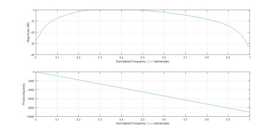
Design a 100th-order bandpass FIR filter using the window method (fir2) to cut frequencies below 15Hz and above 30 Hz in an application where the sampling frequency is 125 Hz. Plot the filter coefficients that defining the filter (stem). Plot the frequency response of the FIR filter designed (freqz)
Homework Answers
MATLAB Code:
clc;
clear all;
close all;
N = 100; % Order = 100
fl = 15; % Lower Cut off Frequency
fh = 30; % Higher Cut off Frequency
fs = 125; % Sampling Frequency
wl = 2*fl/fs; % Digital Lower Cut off Frequency in pi
units
wh = 2*fh/fs; % Digital Higher Cut off Frequency in pi units
w = [0, wl, wh, 1]; % The frequency vector
m = [0, 1, 1, 0]; % The magnitude for Band Pass Filter
h = fir2(100,w,m); % Finding the filter coefficients
n = 0:100; % Range of n for order 100
stem(n,h,'linewidth',2);
grid;
xlabel('n');
ylabel('Amplitude');
title('Filter Coefficients');
figure
freqz(h,1); % Plot the frequency response
After executing, we get

Add Answer to:
Design a 100th-order bandpass FIR filter using the window method
(fir2) to cut frequencies below 15Hz...
1. Design a 10th-order lowpass FIR filter using the window method (fir1) to cut frequencies above...
1. Design a 10th-order lowpass FIR filter using the window method (fir1) to cut frequencies above 30Hz in an application where the sampling frequency is 125 Hz. 2. Plot the filter coefficients that define the filter (stem). 3. Plot the frequency response of the FIR filter designed (freqz) 4. Design a 100th-order lowpass FIR filter using the window method (fir1) to cut frequencies above 30Hz in an application where the sampling frequency is 125 Hz. Plot the filter coefficients that...
7.29. Design a 41-tap bandpass FIR filter with lower and upper cutoff frequencies of 2,500 Hz...
7.29. Design a 41-tap bandpass FIR filter with lower and upper cutoff frequencies of 2,500 Hz and 3,000 Hz, respectively, using the following window functions. Assume a sampling frequency of 8,000 Hz. a. Hanning window function b. Blackman window function. List the FIR filter coefficients and plot the frequency responses for each design. 7.30 Design a 41-tap band reject FIR filter with cutoff frequencies of 2,500 Hz and 3,000 Hz, respectively, using the Hamming window function. Assume a sampling frequency...
3. Design a bandpass FIR filter using Kaiser's formula for filter order, using Hamming window with...
 3. Design a bandpass FIR filter using Kaiser's formula for filter order, using Hamming window with the following specifications: the lower passband and stopband edge frequencies are fpi- 700 Hz, fs1 - 300 Hz, the upper passband and stopband edge frequencies fp2 - 2 kHz fs2 - 2400 Hz, the sampling frequency fs-10 kHz, and 6p-0.03, ando0.004.
1 Design a 4th order causal FIR bandpass filter with cutoff frequencies at 9 kHz and...
 1 Design a 4th order causal FIR bandpass filter with cutoff frequencies at 9 kHz and 18kHz and sampling frequency of 54 kHz. Use a Blackman window. Give precise numerical values for the filter coefficients. The Blackman window has coefficients as shown below (you need choose one window among the three listed below so that a 4 order linear phase filter is designed. (Circle the one you choose). (35pts) Blackman window 1 O.2008 0.8492 0.8492 0.2008 Blackman window 2 0.1300...
Design a 5-tap FIR bandpass filter
Design a 5-tap FIR bandpass filter with a lower cutoff frequency of1,600 Hz, an upper cutoff frequency of 1,800 Hz, and a sampling rateof 8,000 Hz using a. rectangular window functionb. Hamming window function.Determine the transfer function and difference equation of the designedFIR system, and compute and plot the magnitude frequency responsefor Ω= 0, π/4, π/2, 3π/4, and π radians.PLEASE SHOW STEPS CLEARLY
matlab code as well please. 7. (100) Design a bandpass FIR filter with the following Spec:...
 matlab code as well please.
7. (100) Design a bandpass FIR filter with the following Spec: (a) Lower cut off frequency: 1250Hz, (b) lower transition width: 1500Hz, (c) upper cutoff frequency: 2850 Hz, (d) upper transition width: 1300 Hz, (e) stop band attenuation: 60dB, (f) passband ripple 0.02 dB, and (g) sampling frequency: 8000Hz. Your answer needs to include (i) normalized frequencies, (ii) Window type, (iii) order of the filter and their numerical values computed by matlab command firwd(), and...
matlab code as well please.
7. (100) Design a bandpass FIR filter with the following Spec: (a) Lower cut off frequency: 1250Hz, (b) lower transition width: 1500Hz, (c) upper cutoff frequency: 2850 Hz, (d) upper transition width: 1300 Hz, (e) stop band attenuation: 60dB, (f) passband ripple 0.02 dB, and (g) sampling frequency: 8000Hz. Your answer needs to include (i) normalized frequencies, (ii) Window type, (iii) order of the filter and their numerical values computed by matlab command firwd(), and...
Design a linear-phase, bandpass FIR filter using the window-based approach to meet the following specifications: ws,L...
 Design a linear-phase, bandpass FIR filter using the window-based approach to meet the following specifications: ws,L = 0.3T,ap.L = 0.45T,Wp u = 0.65T, "Au-0.8T, mini- mum stopband at (i) Is there a unique window to meet the desired specifications? If not, choose the window with minimum transition width (ii) Plot the magnitude and phase response of the designed filter using MATLAB. (iii Using the MATLAB command firpm, design the same linear-phase bandpass FIR filter via the Parks-McClellan algorithm. Plot the...
Design lowpass IIR filter with the following specifications: Filter order = 2, Butterworth type C...
Design lowpass IIR filter with the following specifications: Filter order = 2, Butterworth type Cut-off frequency=800 Hz Sampling rate =8000 Hz Design using the bilinear z-transform design method Print the lowpass IIR filter coefficients and plot the frequency responses using MATLAB. MATLAB>>freqz(bLP,aLP,512,8000); axis([0 4000 –40 1]); Label and print your graph. What is the filter gain at the cut-off frequency 800 Hz? What are the filter gains for the stopband at 2000 Hz and the passband at 50 Hz based...
7.3. Design a 5-tap FIR lowpass filter with a cutoff frequency of 100 Hz and a...
 7.3. Design a 5-tap FIR lowpass filter with a cutoff frequency of 100 Hz and a sampling rate of 1,000 Hz using a a. rectangular window function b. Hamming window function Determine the transfer function and difference equation of the designed FIR system, and compute and plot the magnitude frequency response for ?--0, ?/4, ?/2, 3r/4, and ? radians.
please answer all the question and print matlab code You need to design bandpass filter with lower cutoff freq. of 1000Hz and upper cutoff freq. of 3000Hz. Sampling freq. 10000Hz. Plot the freq. respo...
please answer all the question and print matlab code You need to design bandpass filter with lower cutoff freq. of 1000Hz and upper cutoff freq. of 3000Hz. Sampling freq. 10000Hz. Plot the freq. response in DB .Use MATLAB as needed a) FIR with Hamming window at least 7 taps b) IIR using Bilinear Transformation method not more than 2end order. c) Compare the frequency response “freqz” plots and which method you recommend and why? 2 graphs on this part. d)...
 3. Design a bandpass FIR filter using Kaiser's formula for filter order, using Hamming window with the following specifications: the lower passband and stopband edge frequencies are fpi- 700 Hz, fs1 - 300 Hz, the upper passband and stopband edge frequencies fp2 - 2 kHz fs2 - 2400 Hz, the sampling frequency fs-10 kHz, and 6p-0.03, ando0.004.
 1 Design a 4th order causal FIR bandpass filter with cutoff frequencies at 9 kHz and 18kHz and sampling frequency of 54 kHz. Use a Blackman window. Give precise numerical values for the filter coefficients. The Blackman window has coefficients as shown below (you need choose one window among the three listed below so that a 4 order linear phase filter is designed. (Circle the one you choose). (35pts) Blackman window 1 O.2008 0.8492 0.8492 0.2008 Blackman window 2 0.1300...
 matlab code as well please.
7. (100) Design a bandpass FIR filter with the following Spec: (a) Lower cut off frequency: 1250Hz, (b) lower transition width: 1500Hz, (c) upper cutoff frequency: 2850 Hz, (d) upper transition width: 1300 Hz, (e) stop band attenuation: 60dB, (f) passband ripple 0.02 dB, and (g) sampling frequency: 8000Hz. Your answer needs to include (i) normalized frequencies, (ii) Window type, (iii) order of the filter and their numerical values computed by matlab command firwd(), and...
matlab code as well please.
7. (100) Design a bandpass FIR filter with the following Spec: (a) Lower cut off frequency: 1250Hz, (b) lower transition width: 1500Hz, (c) upper cutoff frequency: 2850 Hz, (d) upper transition width: 1300 Hz, (e) stop band attenuation: 60dB, (f) passband ripple 0.02 dB, and (g) sampling frequency: 8000Hz. Your answer needs to include (i) normalized frequencies, (ii) Window type, (iii) order of the filter and their numerical values computed by matlab command firwd(), and...
 Design a linear-phase, bandpass FIR filter using the window-based approach to meet the following specifications: ws,L = 0.3T,ap.L = 0.45T,Wp u = 0.65T, "Au-0.8T, mini- mum stopband at (i) Is there a unique window to meet the desired specifications? If not, choose the window with minimum transition width (ii) Plot the magnitude and phase response of the designed filter using MATLAB. (iii Using the MATLAB command firpm, design the same linear-phase bandpass FIR filter via the Parks-McClellan algorithm. Plot the...
 7.3. Design a 5-tap FIR lowpass filter with a cutoff frequency of 100 Hz and a sampling rate of 1,000 Hz using a a. rectangular window function b. Hamming window function Determine the transfer function and difference equation of the designed FIR system, and compute and plot the magnitude frequency response for ?--0, ?/4, ?/2, 3r/4, and ? radians.
Most questions answered within 3 hours.
-
Where is the error in this code sequence?
String s1 = "Hello";
String s2 = "ello";...
asked 10 months ago -
Financial data for Joel de Paris, Inc., for last year
follow:
Joel de Paris, Inc.
Balance...
asked 10 months ago -
Consider this reaction:
Al2(SO4)3 (aq)+ BaCl3
(aq) Al2Cl6 (aq)- +
3BaSO4(s) . What is the...
asked 10 months ago -
Suppose that Savneet is considering increasing her
recent random sample from 20 car rentals to 40...
asked 10 months ago -
Trucks arrive at an unloading terminal at an average rate of 120
per hour.
Trucks arrive...
asked 10 months ago -
Why are methanol and ethanol completely soluble in water while
octanol is not very little soluble....
asked 10 months ago -
A facilities manager at a university reads in a research report
that the mean amount of...
asked 10 months ago -
When the CuSO4 is rehydrated by adding water to the anhydrous
compound, is this an endothermic...
asked 10 months ago -
A ray of sunlight is passing from diamond into crown glass; the
angle of incidence is...
asked 10 months ago -
A block of mass 0.249 kg is placed on top of a light, vertical
spring of...
asked 10 months ago -
how do the kidneys compensate in the presences of acidosis
a) trigger hyperventilate
b) reserve acid...
asked 10 months ago -
Question 501 pts
The rental rate of capital to the firm increases. Which of the
following...
asked 10 months ago