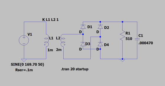
1.Using LTSpice, design a full-wave rectifier (see your textbook) for an input voltage of 120 Vrms...
1.Using LTSpice, design a full-wave rectifier (see your textbook) for an input voltage of 120 Vrms (AC) and an output voltage of 20 V DC. Its design must include a transformer, a diode bridge (4 diodes 1N4001), a load RL = 510 Ω and a capacitor (filter) of 470 μF in parallel with the load.
2.Graph the voltages vL and vD (in LTSpice0, and determine the variation (“ripple”).
Homework Answers
graph uploaded is not the wrong one
in ltspice it takes time to simulate up  to 20 ms time period of 50 Hz signal ,i am
only uploaded graph up to 15 ms de to timing constraints provided
by the HomeworkLib
to 20 ms time period of 50 Hz signal ,i am
only uploaded graph up to 15 ms de to timing constraints provided
by the HomeworkLib

Add Answer to:
1.Using LTSpice, design a full-wave rectifier (see your
textbook) for an input voltage of 120 Vrms...
Q4. Most electronic systems need a dc voltage to work properly. The AC-to-DC power supply system ...
 part g
Q4. Most electronic systems need a dc voltage to work properly. The AC-to-DC power supply system is including a transformer, a rectifier and a capacitor input filter. The AC input voltage is 110 Vrms at 60 Hz. (a) Draw the full wave bridge rectifier circuit with transformer which steps down voltage to safer and lower levels that are more suitable for use with diodes (b) Show how the capacitor input filter connects to the rectifier output in the...
part g
Q4. Most electronic systems need a dc voltage to work properly. The AC-to-DC power supply system is including a transformer, a rectifier and a capacitor input filter. The AC input voltage is 110 Vrms at 60 Hz. (a) Draw the full wave bridge rectifier circuit with transformer which steps down voltage to safer and lower levels that are more suitable for use with diodes (b) Show how the capacitor input filter connects to the rectifier output in the...
1. Power supply (ac to dc) design. [10 pts.] Design a full-wave bridge rectifier circuit to deliv...
 1. Power supply (ac to dc) design. [10 pts.] Design a full-wave bridge rectifier circuit to deliver 10 volts dc with less than 0.1 volt (peak to peak) ripple into a load drawing up to 10 mA. (a) Choose the appropriate ac input voltage from the transformer secondary assuming the usual voltage drops for silicon diodes. (b) Determine the correct capacitor value to ensure the specified ripple in your calculation (c) What fuse value should you select for the primary...
Design a FULL WAVE BRIDGE RECTIFIER circuit that will: Take 120volts ac, 60 hz, sinusoidal wavef...
Design a FULL WAVE BRIDGE RECTIFIER circuit that will: Take 120volts ac, 60 hz, sinusoidal waveform from the wall power and convert it to a “regulated” dc value giving 15 volts +, - 1.0 volts across a 1200-ohm output load resistor with no more than 2% ripple voltage, all at a total component parts cost of less than $175.00 (US$). Your design process/ analysis is to be conducted by hand. Consider for this design task: Assume an ideal transformer and...
Design a FULL WAVE BRIDGE RECTIFIER circuit that will: Take 120volts ac, 60 hz, sinusoidal waveform...
 Design a FULL WAVE BRIDGE RECTIFIER circuit that will:
Take 120volts ac, 60 hz, sinusoidal waveform and convert
it to a “regulated “dc value
giving 12 volts +, - 1 volt across a 2000-ohm output
load resistor with no more than 2%
ripple voltage.
You may assume:
a. An ideal power transformer as discussed in class.
b. For hand computations, you must assume a diode given by
Figure 4.8 page 185.
c. A filter capacitor sized per the textbook equation...
Design a FULL WAVE BRIDGE RECTIFIER circuit that will:
Take 120volts ac, 60 hz, sinusoidal waveform and convert
it to a “regulated “dc value
giving 12 volts +, - 1 volt across a 2000-ohm output
load resistor with no more than 2%
ripple voltage.
You may assume:
a. An ideal power transformer as discussed in class.
b. For hand computations, you must assume a diode given by
Figure 4.8 page 185.
c. A filter capacitor sized per the textbook equation...
Consider the single-phase full-wave rectifier circuit shown below with a sinusoidal input vs 120 Vrms at...
 Consider the single-phase full-wave rectifier circuit shown below with a sinusoidal input vs 120 Vrms at 60 Hz and a load R= 250 TiD DAZ 40 AD AD ww D (a) (b) Consider adding a filter capacitor to the full-wave rectifier in Problem 3 to reduce the output ripple (a) Calculate the minimum value of capacitance required to reduce the output voltage ripple to 1 % of the average value (b) Calculate the average output current (c) Calculate the average...
For your choice of input voltage, load resistor and the value of the ripple voltage (as percent of Vdc) design a circuit for the half-wave rectifier. Assuming the value of Van for the diode, calc...
 For your choice of input voltage, load resistor and the value of the ripple voltage (as percent of Vdc) design a circuit for the half-wave rectifier. Assuming the value of Van for the diode, calculate theoretically all parameters of the rectifier: Vp, Vdc, Idc, C, Isc, PIV and diode conducting interval. Simulate the designed circuit first without the capacitor filter and show on the graphs of the input, output and diode voltages and load and diode currents. Show on the...
It is required to use a FULL-wave rectifier to design a dc power supply that provides...
It is required to use a FULL-wave rectifier to design a dc power supply that provides an average dc output voltage of 15 V. A maximum ripple voltage of ±1 V is allowed on the output voltage. The output voltage will feed a load resistance of 250 Ω. Assume a sinusoidal input voltage with the frequency of 60 Hz. Do not include a Zener diode in your design. (Assume V_D0)* = 0.7 V). a) Draw the circuit diagram. b) Calculate...
1) A classical rectifier uses a standard 120 V/25.2 V 60 Hz transformer. What ideal output...
 1) A classical rectifier uses a standard 120 V/25.2 V 60 Hz transformer. What ideal output DC voltage will result if a single-phase full-wave diode bridge is used with a large capacitor and the input is exactly 120 Vrms? Assume each diode's forward voltage drop is 1 V. Design a capacitor if the load is 50 W and the voltage ripple is 1 V peak-peak?
You need to design a DC power supply that provides an average DC output voltage of...
 You need to design a DC power supply that provides an average DC output voltage of 5V to charge your cellphone. The maximum allowed ripple at the output is ±200 mV. Your cellphone can be modeled as a 1 50Ω load. You have to use a bridge rectifier with four diodes. Note: For calculations, consider constant voltage drop model of the diode with V0 = 0.7V. (a) The charger is designed to use in the US, i.e. transformer primary is...
3. For the regulated power supply shown in Figure 5-3, which is a full-wave bridge rectifier...
 3. For the regulated power supply shown in Figure 5-3, which is a full-wave bridge rectifier containing ter combined with a Zener diode voltage regulator, determine the load voltage VI, load current Ir, source current Is, Zener current Iz and the ripple voltage at the input and output of the regulator, and r(p-p)y respectively, and the ripple frequency fr a fil- VL Ir. Is Iz=. (d-4)1a Ur(p-P) Is V' 1N4002GP Vout = VL + Iz IL 100 V2 120 V...
 part g
Q4. Most electronic systems need a dc voltage to work properly. The AC-to-DC power supply system is including a transformer, a rectifier and a capacitor input filter. The AC input voltage is 110 Vrms at 60 Hz. (a) Draw the full wave bridge rectifier circuit with transformer which steps down voltage to safer and lower levels that are more suitable for use with diodes (b) Show how the capacitor input filter connects to the rectifier output in the...
part g
Q4. Most electronic systems need a dc voltage to work properly. The AC-to-DC power supply system is including a transformer, a rectifier and a capacitor input filter. The AC input voltage is 110 Vrms at 60 Hz. (a) Draw the full wave bridge rectifier circuit with transformer which steps down voltage to safer and lower levels that are more suitable for use with diodes (b) Show how the capacitor input filter connects to the rectifier output in the...
 1. Power supply (ac to dc) design. [10 pts.] Design a full-wave bridge rectifier circuit to deliver 10 volts dc with less than 0.1 volt (peak to peak) ripple into a load drawing up to 10 mA. (a) Choose the appropriate ac input voltage from the transformer secondary assuming the usual voltage drops for silicon diodes. (b) Determine the correct capacitor value to ensure the specified ripple in your calculation (c) What fuse value should you select for the primary...
 Design a FULL WAVE BRIDGE RECTIFIER circuit that will:
Take 120volts ac, 60 hz, sinusoidal waveform and convert
it to a “regulated “dc value
giving 12 volts +, - 1 volt across a 2000-ohm output
load resistor with no more than 2%
ripple voltage.
You may assume:
a. An ideal power transformer as discussed in class.
b. For hand computations, you must assume a diode given by
Figure 4.8 page 185.
c. A filter capacitor sized per the textbook equation...
Design a FULL WAVE BRIDGE RECTIFIER circuit that will:
Take 120volts ac, 60 hz, sinusoidal waveform and convert
it to a “regulated “dc value
giving 12 volts +, - 1 volt across a 2000-ohm output
load resistor with no more than 2%
ripple voltage.
You may assume:
a. An ideal power transformer as discussed in class.
b. For hand computations, you must assume a diode given by
Figure 4.8 page 185.
c. A filter capacitor sized per the textbook equation...
 Consider the single-phase full-wave rectifier circuit shown below with a sinusoidal input vs 120 Vrms at 60 Hz and a load R= 250 TiD DAZ 40 AD AD ww D (a) (b) Consider adding a filter capacitor to the full-wave rectifier in Problem 3 to reduce the output ripple (a) Calculate the minimum value of capacitance required to reduce the output voltage ripple to 1 % of the average value (b) Calculate the average output current (c) Calculate the average...
 For your choice of input voltage, load resistor and the value of the ripple voltage (as percent of Vdc) design a circuit for the half-wave rectifier. Assuming the value of Van for the diode, calculate theoretically all parameters of the rectifier: Vp, Vdc, Idc, C, Isc, PIV and diode conducting interval. Simulate the designed circuit first without the capacitor filter and show on the graphs of the input, output and diode voltages and load and diode currents. Show on the...
 1) A classical rectifier uses a standard 120 V/25.2 V 60 Hz transformer. What ideal output DC voltage will result if a single-phase full-wave diode bridge is used with a large capacitor and the input is exactly 120 Vrms? Assume each diode's forward voltage drop is 1 V. Design a capacitor if the load is 50 W and the voltage ripple is 1 V peak-peak?
 You need to design a DC power supply that provides an average DC output voltage of 5V to charge your cellphone. The maximum allowed ripple at the output is ±200 mV. Your cellphone can be modeled as a 1 50Ω load. You have to use a bridge rectifier with four diodes. Note: For calculations, consider constant voltage drop model of the diode with V0 = 0.7V. (a) The charger is designed to use in the US, i.e. transformer primary is...
 3. For the regulated power supply shown in Figure 5-3, which is a full-wave bridge rectifier containing ter combined with a Zener diode voltage regulator, determine the load voltage VI, load current Ir, source current Is, Zener current Iz and the ripple voltage at the input and output of the regulator, and r(p-p)y respectively, and the ripple frequency fr a fil- VL Ir. Is Iz=. (d-4)1a Ur(p-P) Is V' 1N4002GP Vout = VL + Iz IL 100 V2 120 V...
Most questions answered within 3 hours.
-
Where is the error in this code sequence?
String s1 = "Hello";
String s2 = "ello";...
asked 10 months ago -
Financial data for Joel de Paris, Inc., for last year
follow:
Joel de Paris, Inc.
Balance...
asked 10 months ago -
Consider this reaction:
Al2(SO4)3 (aq)+ BaCl3
(aq) Al2Cl6 (aq)- +
3BaSO4(s) . What is the...
asked 10 months ago -
Suppose that Savneet is considering increasing her
recent random sample from 20 car rentals to 40...
asked 10 months ago -
Trucks arrive at an unloading terminal at an average rate of 120
per hour.
Trucks arrive...
asked 10 months ago -
Why are methanol and ethanol completely soluble in water while
octanol is not very little soluble....
asked 10 months ago -
A facilities manager at a university reads in a research report
that the mean amount of...
asked 10 months ago -
When the CuSO4 is rehydrated by adding water to the anhydrous
compound, is this an endothermic...
asked 10 months ago -
A ray of sunlight is passing from diamond into crown glass; the
angle of incidence is...
asked 10 months ago -
A block of mass 0.249 kg is placed on top of a light, vertical
spring of...
asked 10 months ago -
how do the kidneys compensate in the presences of acidosis
a) trigger hyperventilate
b) reserve acid...
asked 10 months ago -
Question 501 pts
The rental rate of capital to the firm increases. Which of the
following...
asked 10 months ago