AP1. Wm(?)/Va(s)= ?/(? + ?) where the output, ?"(?), is the rotor speed in rad/s and...
AP1.
Wm(?)/Va(s)= ?/(? + ?)
where the output, ?"(?), is the rotor speed in rad/s and the input,
?'(?), is the applied armature
voltage in volts.
A DC motor is being benchmark tested to determine its transfer
function. The input voltage is
held constant at 7 V. At time t = 2.5 seconds, the rotor speed is
40 rad/s. The steady-state
speed of the of motor (? → ∞) is 120 rad/s. \
The answer for this part was (k=2.781, ?=0.162)
Using the result from AP1, create a single script file and
perform the following within it:
a. Using the values determined for k and ?, create the motor
transfer function Wm(?)/Va(s).
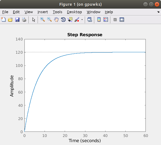
b. Using the step function, plot the transfer function output
response, ?+(?), for a constant
input voltage, ?.(?) = 7 ? from t = 0 to t = 60 seconds.
Label the x-axis and y-axis appropriately.
Homework Answers
Script:
t = 0:0.001:60; % define time variable
syms s; %define symbolic variable s
K = 2.781; a = 0.162;
V = 7;
num = K; % numerator of transfer function
den = sym2poly(s + a); %denominator defined with symbolic variable s
G = tf(num, den); % define G(s)
figure;step(V*G,t); % step response for constant input V=7 volt, t=0 to 60 seconds
Step response plot:
Add Answer to:
AP1.
Wm(?)/Va(s)= ?/(? + ?)
where the output, ?"(?), is the rotor speed in rad/s and...
Problem-5 (20 pts): Consider the DC servo motor shown in Figure-5. Assume that the input of the s...
 Problem-5 (20 pts): Consider the DC servo motor shown in Figure-5. Assume that the input of the system is the applied armature voltage ea and the output is the load shaft position θ2. Assume also the following numerical values for the components: Ra-) Armature winding resistance = 0.2Ω La → Armature winding inductance = 0.1 mH Kb-) Back emf constant 0.05 Vs/rad K > Motor torque constant 0.06 Nm/A Jr Moment of inertia of the rotor of the motor =...
Otor shown below is controlled by the armature voltage va and load torque ease i ngular velocity ...
 otor shown below is controlled by the armature voltage va and load torque ease i ngular velocity w, and ts is the back-emf generated by op a model (first order differential equation) of armature current i in terms velop a model (irst order differential equation) of motor output speed w in terms ta and w as state variables, and va and Ti as inputs, write the state equations the motor. complete the following of motor output speed w and input...
The simplified diagram of a DC motor is shown in Fig. 4. Assume that the rotor has inertia m J an...
 The simplified diagram of a DC motor is shown in Fig. 4. Assume
that the rotor has inertia m J and viscous friction coefficient Bm.
The torque developed by the motor is assumed to be related linearly
to the field current by , m m f T K i where the motor torque
constant m f a K K K I 1 when the armature current a i is assumed
constant (i.e. ) a a i I...
The simplified diagram of a DC motor is shown in Fig. 4. Assume
that the rotor has inertia m J and viscous friction coefficient Bm.
The torque developed by the motor is assumed to be related linearly
to the field current by , m m f T K i where the motor torque
constant m f a K K K I 1 when the armature current a i is assumed
constant (i.e. ) a a i I...
A permanent magnet DC motor is supplied from a 12 V source and turns at 500...
 A permanent magnet DC motor is supplied from a 12 V source and turns at 500 RPM (steady-state) experimentally determined as 0.1 Nms2 and the frictions are negligible. The electrical parameters of the rotor winding are measured 0.82, and 5mH. Obtain the transfer function of the motor by considering the armature voltage as input and shaft speed in rad/s as output. with an armature current of 1A. The moment of inertia is
The answer is ws/va(s) = k/ (( LaS+Ra)(Js+B)+K^2) 7, Derive transfer function (a(s) = Angularvelocity of...
 The answer is ws/va(s) = k/ (( LaS+Ra)(Js+B)+K^2)
7, Derive transfer function (a(s) = Angularvelocity of a DC motor. (1) Aramture voltage Va (s) R. e) i, (C) i,o) v constant (permanent magnet) Armature Field J: inertia B: damping T: load
The answer is ws/va(s) = k/ (( LaS+Ra)(Js+B)+K^2)
7, Derive transfer function (a(s) = Angularvelocity of a DC motor. (1) Aramture voltage Va (s) R. e) i, (C) i,o) v constant (permanent magnet) Armature Field J: inertia B: damping T: load
(30 pts) A D.C. motor is shown below, where the inductance L and the resistance R model the armat...
 (30 pts) A D.C. motor is shown below, where the inductance L and the resistance R model the armature circuit. The voltage Vb represents the back-emf which is proportional to dθ/dt via K. The torque T generated by the motor is proportional to the i via a constant K. The inertia J represents the combined inertia of the motor and load. The viscous friction acting on the output shaft is B 1. pur voltaop a. A. (10 pts) Find the...
D.C. motor is shown below, where the inductance L and the resistance R model the armature circuit. The voltage Vbrepresents the back-emf which is proportional to dθ/dt via Kf. The torque T generated b...
 D.C. motor is shown below, where the inductance
L and the resistance R model the
armature circuit. The voltage
Vbrepresents the back-emf
which is proportional to dθ/dt via
Kf. The torque T
generated by the motor is proportional to the
i via a constant
Kt. In this application, let the
constants Kt =
Kf. The inertia
Jrepresents the combined inertia of the motor and
load. The viscous friction acting on the output shaft is
b. Attached to the shaft is...
D.C. motor is shown below, where the inductance
L and the resistance R model the
armature circuit. The voltage
Vbrepresents the back-emf
which is proportional to dθ/dt via
Kf. The torque T
generated by the motor is proportional to the
i via a constant
Kt. In this application, let the
constants Kt =
Kf. The inertia
Jrepresents the combined inertia of the motor and
load. The viscous friction acting on the output shaft is
b. Attached to the shaft is...
2. (20 points) A field controlled DC motor model is given below where eaſt) is an...
 2. (20 points) A field controlled DC motor model is given below where eaſt) is an applied input voltage, ia(t) is the armature current, Ra and La are the armature resistance and inductance, respectively, e(t) is a back (or counter) emf (electro-motive force) le (t) = K w here K is a motor (torque) constant, t(t) is the torque generated by the motor, w(t) is the angular velocity, 0(t) is the angular position, J represents the rotor inertia and load...
Problem 2: 50pts To monitor the rotation speed of a shaft, a generator motor attachment has...
 Problem 2: 50pts To monitor the rotation speed of a shaft, a generator motor attachment has been suggested. Here a permanent magnet motor, shown below, is directly attached to the shaft. Stator (magnet) Armature winding Bearing Power supply Brush Commutator Rotor A voltmeter is connected to the power supply connection and is calibrated for various voltage-rpm values. a) Determine the governing equations for this system. (use the motor rotation as the input and the voltage generated as the output) b)...
15. Calculate the actual rotor speed, in rad/s, at maximum steady-state torque for the machine gi...
 Example 6C:
15. Calculate the actual rotor speed, in rad/s, at maximum steady-state torque for the machine given in Example 6C for operation as a motor when connected to an electric source of (a) 120 Hz with twice rated voltage, (b) 60 Hz with rated voltage, (c) 30 Hz with one-half rated voltage, and (d) 6 Hz with 10 percent rated voltage. Example 6C. The parameters for the equivalent circuit shown in Fig. 6.8-1 may be calculated by using electromagnetie...
Example 6C:
15. Calculate the actual rotor speed, in rad/s, at maximum steady-state torque for the machine given in Example 6C for operation as a motor when connected to an electric source of (a) 120 Hz with twice rated voltage, (b) 60 Hz with rated voltage, (c) 30 Hz with one-half rated voltage, and (d) 6 Hz with 10 percent rated voltage. Example 6C. The parameters for the equivalent circuit shown in Fig. 6.8-1 may be calculated by using electromagnetie...
 Problem-5 (20 pts): Consider the DC servo motor shown in Figure-5. Assume that the input of the system is the applied armature voltage ea and the output is the load shaft position θ2. Assume also the following numerical values for the components: Ra-) Armature winding resistance = 0.2Ω La → Armature winding inductance = 0.1 mH Kb-) Back emf constant 0.05 Vs/rad K > Motor torque constant 0.06 Nm/A Jr Moment of inertia of the rotor of the motor =...
 otor shown below is controlled by the armature voltage va and load torque ease i ngular velocity w, and ts is the back-emf generated by op a model (first order differential equation) of armature current i in terms velop a model (irst order differential equation) of motor output speed w in terms ta and w as state variables, and va and Ti as inputs, write the state equations the motor. complete the following of motor output speed w and input...
 The simplified diagram of a DC motor is shown in Fig. 4. Assume
that the rotor has inertia m J and viscous friction coefficient Bm.
The torque developed by the motor is assumed to be related linearly
to the field current by , m m f T K i where the motor torque
constant m f a K K K I 1 when the armature current a i is assumed
constant (i.e. ) a a i I...
The simplified diagram of a DC motor is shown in Fig. 4. Assume
that the rotor has inertia m J and viscous friction coefficient Bm.
The torque developed by the motor is assumed to be related linearly
to the field current by , m m f T K i where the motor torque
constant m f a K K K I 1 when the armature current a i is assumed
constant (i.e. ) a a i I...
 A permanent magnet DC motor is supplied from a 12 V source and turns at 500 RPM (steady-state) experimentally determined as 0.1 Nms2 and the frictions are negligible. The electrical parameters of the rotor winding are measured 0.82, and 5mH. Obtain the transfer function of the motor by considering the armature voltage as input and shaft speed in rad/s as output. with an armature current of 1A. The moment of inertia is
 The answer is ws/va(s) = k/ (( LaS+Ra)(Js+B)+K^2)
7, Derive transfer function (a(s) = Angularvelocity of a DC motor. (1) Aramture voltage Va (s) R. e) i, (C) i,o) v constant (permanent magnet) Armature Field J: inertia B: damping T: load
The answer is ws/va(s) = k/ (( LaS+Ra)(Js+B)+K^2)
7, Derive transfer function (a(s) = Angularvelocity of a DC motor. (1) Aramture voltage Va (s) R. e) i, (C) i,o) v constant (permanent magnet) Armature Field J: inertia B: damping T: load
 (30 pts) A D.C. motor is shown below, where the inductance L and the resistance R model the armature circuit. The voltage Vb represents the back-emf which is proportional to dθ/dt via K. The torque T generated by the motor is proportional to the i via a constant K. The inertia J represents the combined inertia of the motor and load. The viscous friction acting on the output shaft is B 1. pur voltaop a. A. (10 pts) Find the...
 D.C. motor is shown below, where the inductance
L and the resistance R model the
armature circuit. The voltage
Vbrepresents the back-emf
which is proportional to dθ/dt via
Kf. The torque T
generated by the motor is proportional to the
i via a constant
Kt. In this application, let the
constants Kt =
Kf. The inertia
Jrepresents the combined inertia of the motor and
load. The viscous friction acting on the output shaft is
b. Attached to the shaft is...
D.C. motor is shown below, where the inductance
L and the resistance R model the
armature circuit. The voltage
Vbrepresents the back-emf
which is proportional to dθ/dt via
Kf. The torque T
generated by the motor is proportional to the
i via a constant
Kt. In this application, let the
constants Kt =
Kf. The inertia
Jrepresents the combined inertia of the motor and
load. The viscous friction acting on the output shaft is
b. Attached to the shaft is...
 2. (20 points) A field controlled DC motor model is given below where eaſt) is an applied input voltage, ia(t) is the armature current, Ra and La are the armature resistance and inductance, respectively, e(t) is a back (or counter) emf (electro-motive force) le (t) = K w here K is a motor (torque) constant, t(t) is the torque generated by the motor, w(t) is the angular velocity, 0(t) is the angular position, J represents the rotor inertia and load...
 Problem 2: 50pts To monitor the rotation speed of a shaft, a generator motor attachment has been suggested. Here a permanent magnet motor, shown below, is directly attached to the shaft. Stator (magnet) Armature winding Bearing Power supply Brush Commutator Rotor A voltmeter is connected to the power supply connection and is calibrated for various voltage-rpm values. a) Determine the governing equations for this system. (use the motor rotation as the input and the voltage generated as the output) b)...
 Example 6C:
15. Calculate the actual rotor speed, in rad/s, at maximum steady-state torque for the machine given in Example 6C for operation as a motor when connected to an electric source of (a) 120 Hz with twice rated voltage, (b) 60 Hz with rated voltage, (c) 30 Hz with one-half rated voltage, and (d) 6 Hz with 10 percent rated voltage. Example 6C. The parameters for the equivalent circuit shown in Fig. 6.8-1 may be calculated by using electromagnetie...
Example 6C:
15. Calculate the actual rotor speed, in rad/s, at maximum steady-state torque for the machine given in Example 6C for operation as a motor when connected to an electric source of (a) 120 Hz with twice rated voltage, (b) 60 Hz with rated voltage, (c) 30 Hz with one-half rated voltage, and (d) 6 Hz with 10 percent rated voltage. Example 6C. The parameters for the equivalent circuit shown in Fig. 6.8-1 may be calculated by using electromagnetie...
Most questions answered within 3 hours.
-
Where is the error in this code sequence?
String s1 = "Hello";
String s2 = "ello";...
asked 11 months ago -
Financial data for Joel de Paris, Inc., for last year
follow:
Joel de Paris, Inc.
Balance...
asked 11 months ago -
Consider this reaction:
Al2(SO4)3 (aq)+ BaCl3
(aq) Al2Cl6 (aq)- +
3BaSO4(s) . What is the...
asked 11 months ago -
Suppose that Savneet is considering increasing her
recent random sample from 20 car rentals to 40...
asked 11 months ago -
Trucks arrive at an unloading terminal at an average rate of 120
per hour.
Trucks arrive...
asked 11 months ago -
Why are methanol and ethanol completely soluble in water while
octanol is not very little soluble....
asked 11 months ago -
A facilities manager at a university reads in a research report
that the mean amount of...
asked 11 months ago -
When the CuSO4 is rehydrated by adding water to the anhydrous
compound, is this an endothermic...
asked 11 months ago -
A ray of sunlight is passing from diamond into crown glass; the
angle of incidence is...
asked 11 months ago -
A block of mass 0.249 kg is placed on top of a light, vertical
spring of...
asked 11 months ago -
how do the kidneys compensate in the presences of acidosis
a) trigger hyperventilate
b) reserve acid...
asked 11 months ago -
Question 501 pts
The rental rate of capital to the firm increases. Which of the
following...
asked 11 months ago