Transient Analysis for Control System Questions Q1) From transient analysis C(s)/R(s)= k/s+a, how do we find...
Transient Analysis for Control System Questions
Q1) From transient analysis C(s)/R(s)= k/s+a, how do we find impulse and unit step response?
Q2) Based on Q1, how do we determine transient and steady state response from impulse and unit step response on what basis? Show graph and examples please
Q3) How to move close loop poles further away from imaginary axis to make time constant smaller to make transient gone?
Homework Answers


Add Answer to:
Transient Analysis for Control System Questions
Q1) From transient analysis C(s)/R(s)= k/s+a, how do we find...
10 Q.1 Figure Q1 shows a speed control system where Gi(s) 0.5s 1' and K(s)kp K(s) G,(s) Figure Q1: Speed Control System a) Determine the transfer function from d to y (4 marks) (b) Assuming the r...
 10 Q.1 Figure Q1 shows a speed control system where Gi(s) 0.5s 1' and K(s)kp K(s) G,(s) Figure Q1: Speed Control System a) Determine the transfer function from d to y (4 marks) (b) Assuming the reference is zero, what is the steady-state error (e-r - y), in this case, you want yss since r 0) due to an unit step disturbance in d? What must the value of k be in order to make the steady-state error less than...
R(s) Q1 (25p). The closed loop control system is shown in the figure. The response of...
 R(s) Q1 (25p). The closed loop control system is shown in the figure. The response of the control system to a unit step reference input is shown in below. C(s) Kp 0.6 S2 + 5s + A 4 a) Find and wn. b) Find Ke and A c) If we use a proportional-integral (PI) controller instead of a proportional (P) controller, how the graph would be expected to change. For two different integral coefficients (bigger Ki_1 and smaller K_2), make...
Q1) Consider an LTI system with frequency response (u) given by (a) Find the impulse response h(0) for this system. [Hint: In case of polynomial over pohnomial frequency domain representation, we...
 Q1) Consider an LTI system with frequency response (u) given by (a) Find the impulse response h(0) for this system. [Hint: In case of polynomial over pohnomial frequency domain representation, we analyce the denominator and use partial fraction expansion to write H() in the form Then we notice that each of these fraction terms is the Fourier of an exponentiol multiplied by a unit step as per the Table J (b) What is the output y(t) from the system if...
Can someone help me with problem 4? You dont need to find the answers for problem...
 Can someone help me with problem 4? You dont need to find the
answers for problem 6. Just use the transfer function from problem
6 to do problem 4.
6. Given the unity feedback system with the forward transfer function KG)H(s + 2)(s + 10) a) b) c) d) e) Sketch the root locus Find the breakaway point Find the gain at the breakaway point If one of the poles of the closed-loop system is at s--11, find the other...
Can someone help me with problem 4? You dont need to find the
answers for problem 6. Just use the transfer function from problem
6 to do problem 4.
6. Given the unity feedback system with the forward transfer function KG)H(s + 2)(s + 10) a) b) c) d) e) Sketch the root locus Find the breakaway point Find the gain at the breakaway point If one of the poles of the closed-loop system is at s--11, find the other...
Recall the disc drive problem from Tutorials, where we demonstrated that the system can be written as e(s)+ 1000 Ge...
 Recall the disc drive problem from Tutorials, where we demonstrated that the system can be written as e(s)+ 1000 Ge(s) s(s2 110s 1250) Figure 2: Disc Drive System Block Diagram We will now try to design a compensator with the requirements that i. Overshoot 1096 ii. Ts S 100ms ii. eramp() s 0.001 Do the following (you may use MATLAB at your leisure, but be sure to explain your logic for your design choices) a) Use MATLAB to draw the...
Consider the following control system: R + Let G(s) s +23-3 and H(s) K where K is some positive c...
 Consider the following control system: R + Let G(s) s +23-3 and H(s) K where K is some positive constant. The transfer function H(s) can be considered a proportional feedback controller. (a) Examine the behavior of the system for different values of K. Try the values K 2, 4, 8. In each case, plot the pole-zero map of the closed-loop system and examine the step response. Comment on the stability of the system. Find the value of K for which...
The impulse invariant approximation of an analogue transfer func- tion G(s) including a model of the...
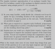 The impulse invariant approximation of an analogue transfer func- tion G(s) including a model of the analogue-to-digital converter in the computer using sample period T = 0.1 seconds, is Q(2) 4.535 x 10⁻³ 2 + 0.905 (z - 1)(2 – 0.7408) (i) In your exam booklet, neatly sketch the z-domain root locus di- agram for Q(2) including location of the asymptotes, and any break-away or break-in points on the real axis. Useful formulae are provided on page 2. 6 marks...
i am needing help with a b c o chris question thanks 1000 O(s) Gc(s) s(s2 110s 1250) Figure 2: Disc Drive System Block D...
 i am needing help with a b c o chris question thanks
1000 O(s) Gc(s) s(s2 110s 1250) Figure 2: Disc Drive System Block Diagram We will now try to design a compensator with the requirements that Overshoot 10% ii. Ts S 100ms II. eramp(oo) s 0.001 Do the following (you may use MATLAB at your leisure, but be sure to explain your logic for your design choices) a) Use MATLAB to draw the root locus when Gc K. Augment...
i am needing help with a b c o chris question thanks
1000 O(s) Gc(s) s(s2 110s 1250) Figure 2: Disc Drive System Block Diagram We will now try to design a compensator with the requirements that Overshoot 10% ii. Ts S 100ms II. eramp(oo) s 0.001 Do the following (you may use MATLAB at your leisure, but be sure to explain your logic for your design choices) a) Use MATLAB to draw the root locus when Gc K. Augment...
Answer the following questions: К R(s) C(s) к, ST1 Find the closed loop transfer function from...
 Answer the following questions: К R(s) C(s) к, ST1 Find the closed loop transfer function from R(s) to C(s) for the system of the diagram above. Draw the root locus for the system in the diagram above as a function of K Draw the unit step response for the system in the diagram above marking the settling time, peak time and maximum output. Find all the possibilities: overdamped, critically damped, underdamped. Find an expression to the steady state error to...
C(8) for the system shown in Figure 1. R(S Find the equivalent transfer function, Geg (s)...
 C(8) for the system shown in Figure 1. R(S Find the equivalent transfer function, Geg (s) 1 Cix) Figure 1. Block diagram 2s+1 s(5s+6Ge(s) = and Figure 2 shows a closed-loop transfer function, where G(s) 2. proper H(s) K+s. Find the overall closed-loop transfer function and express is as rational function. C(s) Ea (s) Controller R(s) +/ Plant G(s) Ge (s) Feedback H(s) Figure 2. Closed loop transfer function Construct the actuation Error Transfer Function associated with the system shown...
 10 Q.1 Figure Q1 shows a speed control system where Gi(s) 0.5s 1' and K(s)kp K(s) G,(s) Figure Q1: Speed Control System a) Determine the transfer function from d to y (4 marks) (b) Assuming the reference is zero, what is the steady-state error (e-r - y), in this case, you want yss since r 0) due to an unit step disturbance in d? What must the value of k be in order to make the steady-state error less than...
 R(s) Q1 (25p). The closed loop control system is shown in the figure. The response of the control system to a unit step reference input is shown in below. C(s) Kp 0.6 S2 + 5s + A 4 a) Find and wn. b) Find Ke and A c) If we use a proportional-integral (PI) controller instead of a proportional (P) controller, how the graph would be expected to change. For two different integral coefficients (bigger Ki_1 and smaller K_2), make...
 Q1) Consider an LTI system with frequency response (u) given by (a) Find the impulse response h(0) for this system. [Hint: In case of polynomial over pohnomial frequency domain representation, we analyce the denominator and use partial fraction expansion to write H() in the form Then we notice that each of these fraction terms is the Fourier of an exponentiol multiplied by a unit step as per the Table J (b) What is the output y(t) from the system if...
 Can someone help me with problem 4? You dont need to find the
answers for problem 6. Just use the transfer function from problem
6 to do problem 4.
6. Given the unity feedback system with the forward transfer function KG)H(s + 2)(s + 10) a) b) c) d) e) Sketch the root locus Find the breakaway point Find the gain at the breakaway point If one of the poles of the closed-loop system is at s--11, find the other...
Can someone help me with problem 4? You dont need to find the
answers for problem 6. Just use the transfer function from problem
6 to do problem 4.
6. Given the unity feedback system with the forward transfer function KG)H(s + 2)(s + 10) a) b) c) d) e) Sketch the root locus Find the breakaway point Find the gain at the breakaway point If one of the poles of the closed-loop system is at s--11, find the other...
 Recall the disc drive problem from Tutorials, where we demonstrated that the system can be written as e(s)+ 1000 Ge(s) s(s2 110s 1250) Figure 2: Disc Drive System Block Diagram We will now try to design a compensator with the requirements that i. Overshoot 1096 ii. Ts S 100ms ii. eramp() s 0.001 Do the following (you may use MATLAB at your leisure, but be sure to explain your logic for your design choices) a) Use MATLAB to draw the...
 Consider the following control system: R + Let G(s) s +23-3 and H(s) K where K is some positive constant. The transfer function H(s) can be considered a proportional feedback controller. (a) Examine the behavior of the system for different values of K. Try the values K 2, 4, 8. In each case, plot the pole-zero map of the closed-loop system and examine the step response. Comment on the stability of the system. Find the value of K for which...
 The impulse invariant approximation of an analogue transfer func- tion G(s) including a model of the analogue-to-digital converter in the computer using sample period T = 0.1 seconds, is Q(2) 4.535 x 10⁻³ 2 + 0.905 (z - 1)(2 – 0.7408) (i) In your exam booklet, neatly sketch the z-domain root locus di- agram for Q(2) including location of the asymptotes, and any break-away or break-in points on the real axis. Useful formulae are provided on page 2. 6 marks...
 i am needing help with a b c o chris question thanks
1000 O(s) Gc(s) s(s2 110s 1250) Figure 2: Disc Drive System Block Diagram We will now try to design a compensator with the requirements that Overshoot 10% ii. Ts S 100ms II. eramp(oo) s 0.001 Do the following (you may use MATLAB at your leisure, but be sure to explain your logic for your design choices) a) Use MATLAB to draw the root locus when Gc K. Augment...
i am needing help with a b c o chris question thanks
1000 O(s) Gc(s) s(s2 110s 1250) Figure 2: Disc Drive System Block Diagram We will now try to design a compensator with the requirements that Overshoot 10% ii. Ts S 100ms II. eramp(oo) s 0.001 Do the following (you may use MATLAB at your leisure, but be sure to explain your logic for your design choices) a) Use MATLAB to draw the root locus when Gc K. Augment...
 Answer the following questions: К R(s) C(s) к, ST1 Find the closed loop transfer function from R(s) to C(s) for the system of the diagram above. Draw the root locus for the system in the diagram above as a function of K Draw the unit step response for the system in the diagram above marking the settling time, peak time and maximum output. Find all the possibilities: overdamped, critically damped, underdamped. Find an expression to the steady state error to...
 C(8) for the system shown in Figure 1. R(S Find the equivalent transfer function, Geg (s) 1 Cix) Figure 1. Block diagram 2s+1 s(5s+6Ge(s) = and Figure 2 shows a closed-loop transfer function, where G(s) 2. proper H(s) K+s. Find the overall closed-loop transfer function and express is as rational function. C(s) Ea (s) Controller R(s) +/ Plant G(s) Ge (s) Feedback H(s) Figure 2. Closed loop transfer function Construct the actuation Error Transfer Function associated with the system shown...
Most questions answered within 3 hours.
-
Where is the error in this code sequence?
String s1 = "Hello";
String s2 = "ello";...
asked 11 months ago -
Financial data for Joel de Paris, Inc., for last year
follow:
Joel de Paris, Inc.
Balance...
asked 11 months ago -
Consider this reaction:
Al2(SO4)3 (aq)+ BaCl3
(aq) Al2Cl6 (aq)- +
3BaSO4(s) . What is the...
asked 11 months ago -
Suppose that Savneet is considering increasing her
recent random sample from 20 car rentals to 40...
asked 11 months ago -
Trucks arrive at an unloading terminal at an average rate of 120
per hour.
Trucks arrive...
asked 11 months ago -
Why are methanol and ethanol completely soluble in water while
octanol is not very little soluble....
asked 11 months ago -
A facilities manager at a university reads in a research report
that the mean amount of...
asked 11 months ago -
When the CuSO4 is rehydrated by adding water to the anhydrous
compound, is this an endothermic...
asked 11 months ago -
A ray of sunlight is passing from diamond into crown glass; the
angle of incidence is...
asked 11 months ago -
A block of mass 0.249 kg is placed on top of a light, vertical
spring of...
asked 11 months ago -
how do the kidneys compensate in the presences of acidosis
a) trigger hyperventilate
b) reserve acid...
asked 11 months ago -
Question 501 pts
The rental rate of capital to the firm increases. Which of the
following...
asked 11 months ago