Force Couples and Moments

Two parallel 60Nforces are applied to a lever as shown. Determine the moment of the couple formed by the two forces:
a) by resolving each force into horizontal and vertical components and adding the moments of the two resulting couples,
b) by using the perpendicular distance between the two forces &
c) by summing the moments of the two forces about point A.
The answer for a, b and c is 12.39 Nm.
Homework Answers
The concepts required to solve this problem are the resolution of vector, moment, and the resultant moment.
Resolution of vector: When a force vector makes an angle with the axis, then the cosine component is along axis and the sine component is along axis.
Moment: The moment is the turning effect of force and is usually defined with respect to a fixed reference point. The moment is obtained by taking the product of force and the perpendicular distance of force from a fixed point.
Resultant moment: The resultant moment of the body about a certain point gives the same effect as the sum of all the moment of the body about the same point. The resultant moment is obtained by adding all the moment acting on the body.
Initially, in the first case, the forces along and direction are calculated by using the resolution of vector concept. Then, by using the moment and the resultant moment concept, find the value of moment of the couple forces.
Similarly, in the second case, the value of moment by the couple forces are calculated by using the concept of moment. Finally, in the third case, the moment about a different point is obtained by calculating the perpendicular distance of forces about that point and then multiplying the perpendicular distance with the force.
The expression for moment is,
Here, and are the force and the perpendicular distance of force from a fixed point.
Resolving vector into its components: Consider a vector acting at a point making an angle with the positive axis.
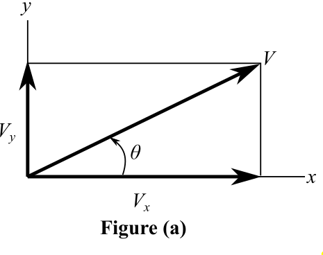
The expression for the component of vector in direction is,
Similarly, the expression for the component of vector in direction is,
Consider the moments acting on the body about a point as and . Then, write the expression of resultant moment about point .
Sign convention: Take the moment in clockwise direction as positive and moment in anticlockwise as negative. This sign convention is used throughout the solution.
(a)
Consider the forces acting at point and as and . The force makes an angle of with the axis. Also, the angle made by the rod with the horizontal is . Thus, from the simple geometry, the angle made by the force with the rod is taken as . Similarly, the force makes an angle of with the rod and with the horizontal axis.
Draw the diagram showing the force components along and axis.
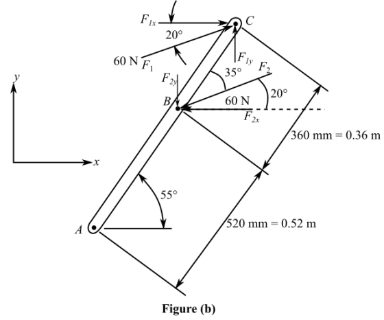
Now, consider the couple forces. Both the forces are equal and opposite in sign. Consider the origin at point . Resolve the force into horizontal and vertical component. Calculate the component of force .
Substitute for .
Similarly, calculate the component of force .
Substitute for .
From the definition of moment, the distance should be perpendicular to the force . The distance between the couple forces is given by . Also, from Figure (b), it is clear that the vertical component of length gives the perpendicular distance of the force .
Since, the angle between the force and the distance is given by . Thus, the angle between the rod length with the vertical is . This gives the vertical component of length as and horizontal component as . Draw the diagram for the and component of force and the perpendicular distance.
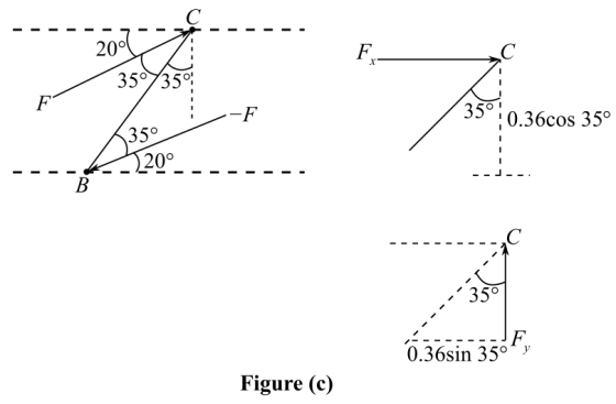
Calculate the moment by the component of force.
Substitute for and for .
The moment in direction is clockwise as shown in Figure (c), and is therefore, taken as positive.
Similarly, calculate the moment by the component of force.
Substitute for and for .
The moment in direction is anticlockwise as shown in Figure (c), and is therefore, taken as negative.
Calculate the moment of the couple.
Substitute for , and for .
(b)
Consider the couple forces. The length of the rod is . Also, the rod is at an angle of from the force . Thus, the perpendicular component of distance between the forces is given by . Draw the diagram showing the perpendicular force between the couple forces.

Calculate the moment of the couple by using the perpendicular distance between the two forces.
Substitute for and for .
(c)
To calculate the moment about point , both the couple forces need to be considered as both are acting at a different point than point . Consider the force acting at point . The distance of the point and is given as that is . Draw the diagram showing the perpendicular distance of force from a fixed point .
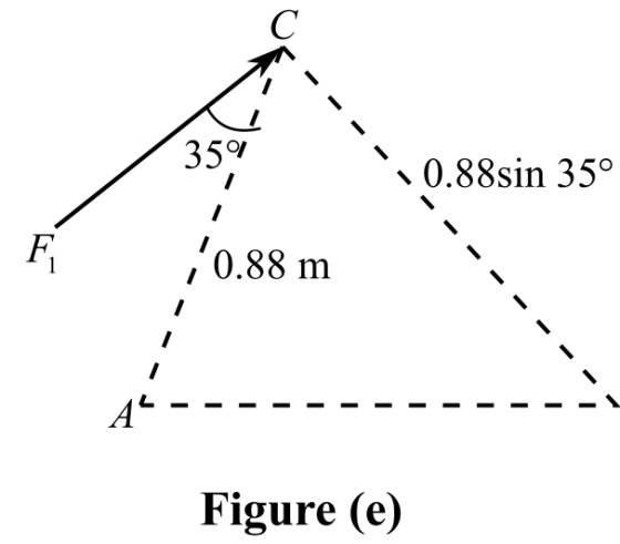
Thus, the perpendicular distance of force is given by . Calculate the moment by the force .
Substitute for and for .
Here, the moment by the force is clockwise and is therefore, taken as positive.
Now, the force acts at point . The distance between point and is given by . Draw the diagram showing the perpendicular distance of force from a fixed point .
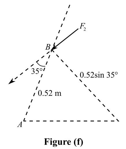
From Figure (f), the angle made by the rod with the force is . Thus, the perpendicular distance is given by . Calculate the moment by the force .
Substitute for and for .
Here, the moment by the force is anticlockwise and is therefore, taken as negative.
Calculate the moment by the couple forces about point .
Substitute for and for .
Ans: Part a
The moment of the couple in this case is .
Part bThe moment by the couple force in this case is .
Part cThe moment of the couple forces about point is .
Find the moment of the couple formed by the two forces (a) by resolving each force...
 Find the moment of the couple formed by the two forces (a) by resolving each force into horizontal and vertical components and adding the moments of the two resulting couples, (b) by using the perpendicular distance between the two forces, (c) and by summing the moments of the two forces about the pin. (Your answers need to be the same to all three.) (d) Why is your answer not equal to 100 2? 100 lb 4 3 2 in 5...
Force Couples and Moments
 Shafts A and B connect the gearbox to the wheel assemblies of a tractor, and shaft C connects it to the engine. Shafts A and B lie in the vertical yz plane, while shaft C is directed along the x-axis. Replace the couples applied to the shafts with a single equivalent couple, specifying its magnitude and direction of its axis.Answer is: M= 2860Nm= 113.0 degrees= 92.7 degrees= 23.2 degrees
Please solve all the questions. 120 N Question No. 1: A 120-N force is applied to...
 Please solve all the questions.
120 N Question No. 1: A 120-N force is applied to the control rod AB as shown. Knowing that the length of the rod is 0.6 m: 1. Determine the moment of the force about point B by resolving the force into: a. components along AB and in a direction perpendicular to AB. b. horizontal and vertical components. 2. Determine the horizontal force at A which creates the same moment. Question No. 2: Knowing that...
Please solve all the questions.
120 N Question No. 1: A 120-N force is applied to the control rod AB as shown. Knowing that the length of the rod is 0.6 m: 1. Determine the moment of the force about point B by resolving the force into: a. components along AB and in a direction perpendicular to AB. b. horizontal and vertical components. 2. Determine the horizontal force at A which creates the same moment. Question No. 2: Knowing that...
How can the system of forces and moments be simplified with a single force and couple...
 How can the system of forces and moments be simplified with a single force and couple moment acting at the origin of the axis? 400 N.m 250 N.m 1200 N 750N 125 N 350 N 60° C GE150 Nm 1.6 m .4K D B 3.2m- 2.0m2.4m-4 35- 800N 720 N.m
Question 3 points Save Answer An angle bracket is subjected to the forces and couple as shown below. Consider clockwise from horizontal as to be positive for moments and angles. Detemine the equ...
 Question 3 points Save Answer An angle bracket is subjected to the forces and couple as shown below. Consider clockwise from horizontal as to be positive for moments and angles. Detemine the equivalent force-couple system at A. 30cm 200N 150 N 13 em 15 cm 50 N-m 150 N 92 N at 174.1-103 Nm 114 N at 15350 Nm 292 N at-5.9, 103 Nm 333 N at 42.9, 53 Nm Question2 3 points Save Answer The loading shown requires a...
please explain even small steps and im having trouble with the moments so please explain that...
 please explain even small steps and im having trouble with the
moments so please explain that too thanks
(6) The forces and couples shown are applied to two screws as a piece sheet metal is fastened to a block of wood. Reduce the forces and the couples to an equivalent wrench, and determine (a) the resultant R. (b) the pitch of the wrench, (c) the point where the axis of the wrench intersects the xz plane. 6 Nm 375 mm...
please explain even small steps and im having trouble with the
moments so please explain that too thanks
(6) The forces and couples shown are applied to two screws as a piece sheet metal is fastened to a block of wood. Reduce the forces and the couples to an equivalent wrench, and determine (a) the resultant R. (b) the pitch of the wrench, (c) the point where the axis of the wrench intersects the xz plane. 6 Nm 375 mm...
A 43 N horizontal force is applied to the handle of the industrial water valve as shown. The force is perpendicular to t...
 A 43 N horizontal force is applied to the handle of the
industrial water valve as shown. The force is perpendicular to the
vertical place containing line OA of the handle. Determine the
equivalent force- couple system at point O.
A 43-N horizontal force is applied to the handle of the industrial water valve as shown. The force is perpendicular to the vertical plane containing line OA of the handle. Determine the equivalent force-couple system at point O. 155 mm...
A 43 N horizontal force is applied to the handle of the
industrial water valve as shown. The force is perpendicular to the
vertical place containing line OA of the handle. Determine the
equivalent force- couple system at point O.
A 43-N horizontal force is applied to the handle of the industrial water valve as shown. The force is perpendicular to the vertical plane containing line OA of the handle. Determine the equivalent force-couple system at point O. 155 mm...
The beam ABC has a mass of 78.0 kg and is supported by the rope BDC...
 The beam ABC has a mass of 78.0 kg and is supported by the rope
BDC that runs through the frictionless pulley at D. The winch at CC
has a mass of 44.5 kg. The tension in the rope acts on the beam at
points B and C and counteracts the moments due to the beam's weight
(acting vertically at the midpoint of its length) and the weight of
the winch (acting vertically at point C) such that the resultant...
The beam ABC has a mass of 78.0 kg and is supported by the rope
BDC that runs through the frictionless pulley at D. The winch at CC
has a mass of 44.5 kg. The tension in the rope acts on the beam at
points B and C and counteracts the moments due to the beam's weight
(acting vertically at the midpoint of its length) and the weight of
the winch (acting vertically at point C) such that the resultant...
Question 1: A 45-N vertical force P is applied at A to the bracket shown, which...
 Question 1: A 45-N vertical force P is applied at A to the bracket shown, which is held by screws at B and C (a) Replace P with an equivalent force-couple system at B. (b) Find the two horizontal forces at B and C that are equivalent to the couple obtained in part a. 2 cm 3 cm Figure 1
The figure shows a mechanical device in which force (s) are applied parallel to and away...
 The figure shows a mechanical device in which force
(s) are applied parallel to and away from the axis of the main,
beam-like part. The device is supported by bearings at the
locations marked with an X, which can provide reaction forces in
any direction perpendicular to the axis of the beam. One of the
bearings has the capability of resisting horizontally directed
forces
1. Break the compound beam into parts consisting of each of the
straight components.
2. Show...
The figure shows a mechanical device in which force
(s) are applied parallel to and away from the axis of the main,
beam-like part. The device is supported by bearings at the
locations marked with an X, which can provide reaction forces in
any direction perpendicular to the axis of the beam. One of the
bearings has the capability of resisting horizontally directed
forces
1. Break the compound beam into parts consisting of each of the
straight components.
2. Show...
 Find the moment of the couple formed by the two forces (a) by resolving each force into horizontal and vertical components and adding the moments of the two resulting couples, (b) by using the perpendicular distance between the two forces, (c) and by summing the moments of the two forces about the pin. (Your answers need to be the same to all three.) (d) Why is your answer not equal to 100 2? 100 lb 4 3 2 in 5...
 Please solve all the questions.
120 N Question No. 1: A 120-N force is applied to the control rod AB as shown. Knowing that the length of the rod is 0.6 m: 1. Determine the moment of the force about point B by resolving the force into: a. components along AB and in a direction perpendicular to AB. b. horizontal and vertical components. 2. Determine the horizontal force at A which creates the same moment. Question No. 2: Knowing that...
Please solve all the questions.
120 N Question No. 1: A 120-N force is applied to the control rod AB as shown. Knowing that the length of the rod is 0.6 m: 1. Determine the moment of the force about point B by resolving the force into: a. components along AB and in a direction perpendicular to AB. b. horizontal and vertical components. 2. Determine the horizontal force at A which creates the same moment. Question No. 2: Knowing that...
 How can the system of forces and moments be simplified with a single force and couple moment acting at the origin of the axis? 400 N.m 250 N.m 1200 N 750N 125 N 350 N 60° C GE150 Nm 1.6 m .4K D B 3.2m- 2.0m2.4m-4 35- 800N 720 N.m
 Question 3 points Save Answer An angle bracket is subjected to the forces and couple as shown below. Consider clockwise from horizontal as to be positive for moments and angles. Detemine the equivalent force-couple system at A. 30cm 200N 150 N 13 em 15 cm 50 N-m 150 N 92 N at 174.1-103 Nm 114 N at 15350 Nm 292 N at-5.9, 103 Nm 333 N at 42.9, 53 Nm Question2 3 points Save Answer The loading shown requires a...
 please explain even small steps and im having trouble with the
moments so please explain that too thanks
(6) The forces and couples shown are applied to two screws as a piece sheet metal is fastened to a block of wood. Reduce the forces and the couples to an equivalent wrench, and determine (a) the resultant R. (b) the pitch of the wrench, (c) the point where the axis of the wrench intersects the xz plane. 6 Nm 375 mm...
please explain even small steps and im having trouble with the
moments so please explain that too thanks
(6) The forces and couples shown are applied to two screws as a piece sheet metal is fastened to a block of wood. Reduce the forces and the couples to an equivalent wrench, and determine (a) the resultant R. (b) the pitch of the wrench, (c) the point where the axis of the wrench intersects the xz plane. 6 Nm 375 mm...
 A 43 N horizontal force is applied to the handle of the
industrial water valve as shown. The force is perpendicular to the
vertical place containing line OA of the handle. Determine the
equivalent force- couple system at point O.
A 43-N horizontal force is applied to the handle of the industrial water valve as shown. The force is perpendicular to the vertical plane containing line OA of the handle. Determine the equivalent force-couple system at point O. 155 mm...
A 43 N horizontal force is applied to the handle of the
industrial water valve as shown. The force is perpendicular to the
vertical place containing line OA of the handle. Determine the
equivalent force- couple system at point O.
A 43-N horizontal force is applied to the handle of the industrial water valve as shown. The force is perpendicular to the vertical plane containing line OA of the handle. Determine the equivalent force-couple system at point O. 155 mm...
 The beam ABC has a mass of 78.0 kg and is supported by the rope
BDC that runs through the frictionless pulley at D. The winch at CC
has a mass of 44.5 kg. The tension in the rope acts on the beam at
points B and C and counteracts the moments due to the beam's weight
(acting vertically at the midpoint of its length) and the weight of
the winch (acting vertically at point C) such that the resultant...
The beam ABC has a mass of 78.0 kg and is supported by the rope
BDC that runs through the frictionless pulley at D. The winch at CC
has a mass of 44.5 kg. The tension in the rope acts on the beam at
points B and C and counteracts the moments due to the beam's weight
(acting vertically at the midpoint of its length) and the weight of
the winch (acting vertically at point C) such that the resultant...
 Question 1: A 45-N vertical force P is applied at A to the bracket shown, which is held by screws at B and C (a) Replace P with an equivalent force-couple system at B. (b) Find the two horizontal forces at B and C that are equivalent to the couple obtained in part a. 2 cm 3 cm Figure 1
 The figure shows a mechanical device in which force
(s) are applied parallel to and away from the axis of the main,
beam-like part. The device is supported by bearings at the
locations marked with an X, which can provide reaction forces in
any direction perpendicular to the axis of the beam. One of the
bearings has the capability of resisting horizontally directed
forces
1. Break the compound beam into parts consisting of each of the
straight components.
2. Show...
The figure shows a mechanical device in which force
(s) are applied parallel to and away from the axis of the main,
beam-like part. The device is supported by bearings at the
locations marked with an X, which can provide reaction forces in
any direction perpendicular to the axis of the beam. One of the
bearings has the capability of resisting horizontally directed
forces
1. Break the compound beam into parts consisting of each of the
straight components.
2. Show...
Most questions answered within 3 hours.
-
Where is the error in this code sequence?
String s1 = "Hello";
String s2 = "ello";...
asked 11 months ago -
Financial data for Joel de Paris, Inc., for last year
follow:
Joel de Paris, Inc.
Balance...
asked 11 months ago -
Consider this reaction:
Al2(SO4)3 (aq)+ BaCl3
(aq) Al2Cl6 (aq)- +
3BaSO4(s) . What is the...
asked 11 months ago -
Suppose that Savneet is considering increasing her
recent random sample from 20 car rentals to 40...
asked 11 months ago -
Trucks arrive at an unloading terminal at an average rate of 120
per hour.
Trucks arrive...
asked 11 months ago -
Why are methanol and ethanol completely soluble in water while
octanol is not very little soluble....
asked 11 months ago -
A facilities manager at a university reads in a research report
that the mean amount of...
asked 11 months ago -
When the CuSO4 is rehydrated by adding water to the anhydrous
compound, is this an endothermic...
asked 11 months ago -
A ray of sunlight is passing from diamond into crown glass; the
angle of incidence is...
asked 11 months ago -
A block of mass 0.249 kg is placed on top of a light, vertical
spring of...
asked 11 months ago -
how do the kidneys compensate in the presences of acidosis
a) trigger hyperventilate
b) reserve acid...
asked 11 months ago -
Question 501 pts
The rental rate of capital to the firm increases. Which of the
following...
asked 11 months ago