Determine the force in a member of the loaded truss.
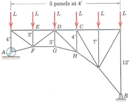
Determine the force in member DG of the loaded truss.
Homework Answers
Concepts and reason
Truss:
A truss is a structure or frame that comprises two force members assembled in different configurations. The entire structure acts as a single member ultimately. A truss is an equilibrium body with the combination of various slender members to form a structured body. Method of joints:
It is a concept used to find the forces in the truss members according to which the sum of forces acting at a joint is equal to zero. Method of sections:
The method of sections is used to calculate the forces in members. It involves the cutting of the truss into sections and then solving the section for static equilibrium conditions. The section is cut such that the members sectioned are the members whose force is exposed on solving. A maximum of three forces (unknowns) can be solved using the three equilibrium equations from the sections' method. First, use moments and equilibrium conditions to form equations to calculate reaction force at the supports. Then use the section's method to cut the truss into sections and solve the section for moment condition. Use the joints' method to calculate the force in each member and assume the forces in that joint as tension, then use equilibrium conditions for forces and moments to form equations to calculate the force in each member. The type of force is decided based on the sign obtained in the final answer. If the answer has a negative sign, it is said to be in compression instead; if it has a positive sign, it is in tension.
Fundamentals
Support reactions:
If there is a force acting by support, the translational movement of the object is restricted or prevented. Then the force developed is called a support reaction. Main types of supports:
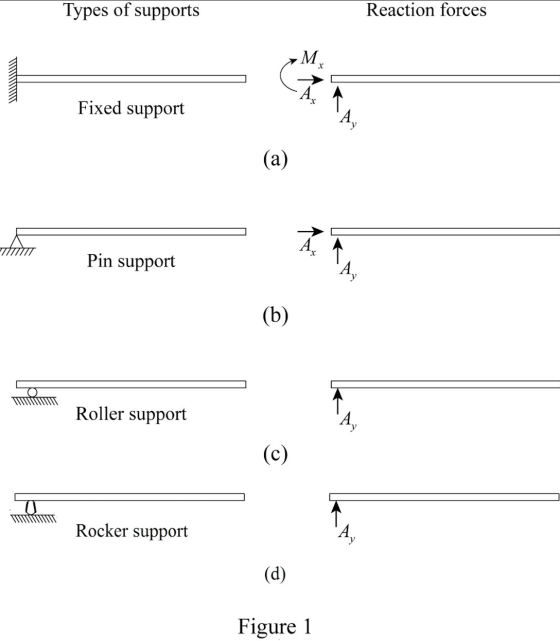
Fixed support:
It prevents rotational, horizontal, and vertical translation. It is shown in Figure \((1\) a) Pinned support:
This support prevents horizontal and vertical translation. It is shown in Figure \((1 \mathrm{~b})\). Roller support:
This support can't prevent the rotation or horizontal movement but can only provide vertical support reaction to the surface as shown in Figure Rocker support:
This support is almost similar to the rocker and will have an only vertical force acting as shown in Figure \((1 \mathrm{~d})\) Force moment:
The magnitude of the moment can be determined by the product of force and the perpendicular distance to the force. Write the equilibrium of forces along the \(x\) -axis. \(\sum F_{x}=0\)
Here, the sum of forces along the \(x\) -direction is \(\sum F_{x}\)
Write the equilibrium of forces along the \(\mathrm{y}\) -axis. \(\sum F_{y}=0\)
Here, the sum of forces along the y-direction is \(\sum F_{y}\). The moment is the product of force and its distance from the point. \(M=F d\)
Here, moment is \(M\), force is \(F\) and distance is \(d\). In equilibrium condition, the summation of moment acting about any point will be equal to zero. \(\sum M=0\)
General sign conventions for a moment:
The moment is considered as negative in a clockwise direction and positive in a counter-clockwise direction.
Draw the free body diagram as shown in Figure (2).
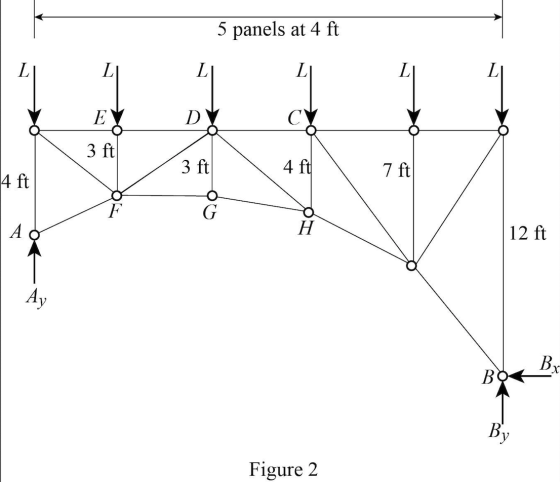
From Figure (2) calculate the moment about \(B\).
\(\sum M_{B}=0\)
\(-L(4 \mathrm{ft})-L(8 \mathrm{ft})-L(12 \mathrm{ft})-L(16 \mathrm{ft})-L(20 \mathrm{ft})+A_{y}(20 \mathrm{ft})=0\)
\(-L(60 \mathrm{ft})=-A_{y}(20 \mathrm{ft})\)
\(A_{y}=3 L\)
From Figure
(2) calculate the sum of vertical forces to obtain the reaction force \(B_{y}\)
\(\sum F_{y}=0\)
\(A_{y}+B_{y}=6 L\)
Substitute \(3 L\) for \(A_{y}\)
\(3 L+B_{y}=6 L\)
\(B_{y}=3 L\)
The free-body diagram is drawn to find the support reactions. The support reaction is determined by taking a moment about
point \(B\) and by the sum of forces along the vertical direction is calculated to obtain the vertical component of the reaction force at support B.
The free-body diagram of the left portion of the section \(a-a\) on the truss is shown in Figure (3).
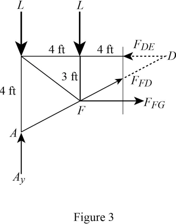
From Figure (3), calculate the moment about point \(D\).
\(\sum M_{D}=0\)
\(-F_{F G}(3 \mathrm{ft})-L(4 \mathrm{ft})-L(8 \mathrm{ft})+A_{y}(8 \mathrm{ft})=0\)
Draw the forces acting at joint G as in Figure (4)
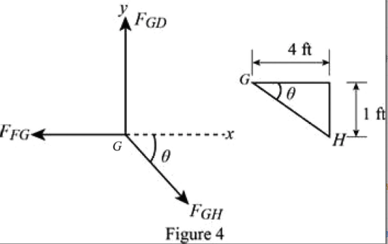
From Figure (4) apply equilibrium of horizontal forces acting on joint G.
\(\sum F_{x}=0\)
\(-F_{F G}+F_{G H} \cos \theta=0\)
\(F_{F G}=F_{G H} \cos \theta\)
From Figure \((4),\) obtain \((\theta)\) at the joint \(G\)
\(\tan \theta=\frac{1}{4}\)
\(\theta=\tan ^{-1}\left(\frac{1}{4}\right)\)
\(\theta=14.04^{\circ}\)
Substitute \(F_{G H} \cos \theta\) for \(F_{F G}\) in Equation (1) \(-\left(F_{G H} \cos \theta\right)(3 \mathrm{ft})-L(4 \mathrm{ft})-L(8 \mathrm{ft})+A_{y}(8 \mathrm{ft})=0\)
Plug-in \(14.04^{\circ}\) for \(\theta\), and \(3 L\) for \(A_{y}\) in Equation (2) \(-F_{G H}\left(\cos 14.04^{\circ}\right)(3 \mathrm{ft})-L(4 \mathrm{ft})-L(8 \mathrm{ft})+(3 L)(8 \mathrm{ft})=0\)
\(-F_{G H}(2.91 \mathrm{ft})+L(12 \mathrm{ft})=0\)
\(F_{G H}=4.12 L\)
The truss is sectioned on the left side. Properties of the right-angled triangle are used to calculate angle \(\theta\) and the member force.
\(F_{G I I}\) is calculated by taking a moment about point \(D\).
Write the equilibrium of forces in \(y\) -axis using Figure (4) . \(\sum F_{y}=0\)
\(-F_{G H} \sin \theta+F_{D G}=0\)
Substitute \(14.04^{\circ}\) for \(\theta\), and \(4.12 L\) for \(F_{G I I}\)
\(-(4.12 L)\left(\sin 14.04^{\circ}\right)+F_{D G}=0\)
\(F_{D G}=1 L\) (Tension)
The force in the \(D G\) member of loaded truss \(\left(F_{D G}\right)\) is \(1 L\) (Tension).
The force relation is obtained by taking the equilibrium of force along the vertical direction using Figure (4). Calculate the member force \(F_{D G}\) by substituting the angle \(\theta\) and force \(F_{G I I}\) in the relation.
The force in the \(D G\) member of loaded truss \(\left(F_{D G}\right)\) is \(1 L\) (Tension).
Determine the force in member BE of the loaded truss. The force is positive if in...
 Determine the force in member BE of the loaded truss. The force is positive if in tension, negative if in compression.
Determine the force in each member of the loaded truss.
 Determine the force in each member of the loaded truss. The forces are positive if in tension, negative if in compression.
Determine the force in the member CK of the loaded truss
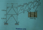 Determine the force in the member CK of the loaded truss. Ans. CK = 9290 N (Compression)Please show detailed steps in solving for force.
Determine the force in member BE of the loaded truss. The force is positive if in...
 Determine the force in member BE of the loaded truss. The force is positive if in tension, negative if in compression. 6 KN 4 KN 8 kN Answer: BE = KN
Determine the force in member AE of the loaded truss. The force is positive if in...
 Determine the force in member AE of the loaded truss. The force is positive if in tension, negative if in compression. (2.8 kN 3.0 KN)
Determine the force in member AE of the loaded truss. The force is positive if in...
 Determine the force in member AE of the loaded truss. The force is positive if in tension, negative if in compression. ( 3.6 kN 2.4 kN )
help pls Determine the force in member BE of the loaded truss. The force is positive...
 help pls
Determine the force in member BE of the loaded truss. The force is positive if in tension, negative if in compression m F 1 m 459 450 2.7 kN 6.0 kN
help pls
Determine the force in member BE of the loaded truss. The force is positive if in tension, negative if in compression m F 1 m 459 450 2.7 kN 6.0 kN
Determine the force in each member of the loaded truss. The forces are positive if in tension, ne...
 Determine the force in each member of the loaded truss. The forces are positive if in tension, negative if in compression
Determine the force in member DK of the loaded overhead sign truss. The force is positive...
 Determine the force in member DK of the loaded overhead sign truss. The force is positive if in tension, negative if in compression. 6 panels at 14: RS 8 kips 6 kips 4 kips 31' V. Answer: DK = kips
Find force in each member of truss
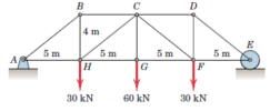 Determine the force in each member of the loaded truss. Make use of the symmetry of the truss and of the loading.
 Determine the force in member BE of the loaded truss. The force is positive if in tension, negative if in compression. 6 KN 4 KN 8 kN Answer: BE = KN
 help pls
Determine the force in member BE of the loaded truss. The force is positive if in tension, negative if in compression m F 1 m 459 450 2.7 kN 6.0 kN
help pls
Determine the force in member BE of the loaded truss. The force is positive if in tension, negative if in compression m F 1 m 459 450 2.7 kN 6.0 kN
 Determine the force in each member of the loaded truss. The forces are positive if in tension, negative if in compression
 Determine the force in member DK of the loaded overhead sign truss. The force is positive if in tension, negative if in compression. 6 panels at 14: RS 8 kips 6 kips 4 kips 31' V. Answer: DK = kips
Most questions answered within 3 hours.
-
Where is the error in this code sequence?
String s1 = "Hello";
String s2 = "ello";...
asked 11 months ago -
Financial data for Joel de Paris, Inc., for last year
follow:
Joel de Paris, Inc.
Balance...
asked 11 months ago -
Consider this reaction:
Al2(SO4)3 (aq)+ BaCl3
(aq) Al2Cl6 (aq)- +
3BaSO4(s) . What is the...
asked 11 months ago -
Suppose that Savneet is considering increasing her
recent random sample from 20 car rentals to 40...
asked 11 months ago -
Trucks arrive at an unloading terminal at an average rate of 120
per hour.
Trucks arrive...
asked 11 months ago -
Why are methanol and ethanol completely soluble in water while
octanol is not very little soluble....
asked 11 months ago -
A facilities manager at a university reads in a research report
that the mean amount of...
asked 11 months ago -
When the CuSO4 is rehydrated by adding water to the anhydrous
compound, is this an endothermic...
asked 11 months ago -
A ray of sunlight is passing from diamond into crown glass; the
angle of incidence is...
asked 11 months ago -
A block of mass 0.249 kg is placed on top of a light, vertical
spring of...
asked 11 months ago -
how do the kidneys compensate in the presences of acidosis
a) trigger hyperventilate
b) reserve acid...
asked 11 months ago -
Question 501 pts
The rental rate of capital to the firm increases. Which of the
following...
asked 11 months ago