Please help!!! Force-couple system- mcgraw 3.83
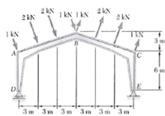
The roof of a building frame is subjected to the wind loading shown. Determine:
a the equivalent force-couple system at D
b the resultant of the loading and its line of action
Homework Answers
Free body diagram of the roof:

As all the left hand sides are parallel to each other, and all the right hand side forces are parallel to each other, all the left hand side forces will have same unit vector and all the right hand forces will have the same unit vector.
From the figure, it is clear that,

Unit vector of the left hand side forces, which lie on the line AB,

Unit vector of the right hand side forces, which lie on the line BC,

As the points F and G divide the segment AB into equal parts in the horizontal direction, same must happen with the case of vertical division. Similarly the points H and I divide the segment BC into equal parts in the vertical direction.
Coordinates of the points,


Force acting through A,

Similarly finding the remaining forces, we get

(a)
Resultant force of all the loading,

Moment caused by all of the forces at D,

Hence, the resultant couple force system at the point D is  and
and 
b)
To find the distance of the line of action of the resultant, we have to divide the magnitude total resultant moment with the magnitude of the resultant force.

As the moment is in the positive z-direction or in other words anti clock wise, in order to create that moment, line of action of the resultant force must be 6 m below the point D.
Hence, the distance of the line of action from the point D is  .
.
Force-couple system
 A couple of magnitude M = 54 lb. in and the three forces shown are applied to an angle bracket.(a) Find the equivalent force-couple system (resultant force-couple) located at Point B.(b) Determine the resultant force couple located at Point C.(c) Determine locations, (x,y), where the resultant force-couple system consists only the net force but no resultant moment, i.e = Moment R = 0. Please definecoordinates first.
Replace the given loads with an equivalent force-couple system at O by specifying the resultant R...
 Replace the given loads with an equivalent force-couple system at O by specifying the resultant R and couple Mo. Next, determine the equation for the line of action of the stand-alone resultant force R. 1.1 m 0.30 m J001 0.7 /5.4 kN / m m1.6 m 75 14 kN-m 10.7 kN 7.0 kN0.30 m Answers: Equivalent force-couple system at O R = 8.79 +2.355 kN Mo =T 19.1502 KN·m The equation for the line of action of the stand-alone resultant...
Replace the loading system shown by an equivalent resultant force and couple moment acting at point A.
 Replace the loading system shown by an equivalent resultant force and couple moment
acting at point A.
Replace the loading system shown by an equivalent resultant force and couple moment
acting at point A.
Replace the loading system by an equivalent resultant force and couple moment at 0. X 2016...
 Replace the loading system by an equivalent resultant force and
couple moment at 0.
X 2016 aft В F = (21-4j +56)1b -24 || 1-244t-aft Mo 10 16.67 Us So16 Replace the loading system by on equivalent resultant force and couple moment at o.
Replace the loading system by an equivalent resultant force and
couple moment at 0.
X 2016 aft В F = (21-4j +56)1b -24 || 1-244t-aft Mo 10 16.67 Us So16 Replace the loading system by on equivalent resultant force and couple moment at o.
The distributed loads and couple act on the frame shown in the figure. Determine the following:...
 The distributed loads and couple act on the frame shown in the figure. Determine the following: a) Reduce the load system into a single resultant force and resulting moment acting at point B. b) Reduce this load system to a single resultant force and determine where this resultants line of action intersects member BC, measured from C.
Replace the loading system shown by an equivalent resultant force and couple moment acting at point...
 Replace the loading system shown by an equivalent resultant
force and couple moment acting at point A.
If possible please show steps, Thanks!
50 Iь 50 lb
Replace the loading system shown by an equivalent resultant
force and couple moment acting at point A.
If possible please show steps, Thanks!
50 Iь 50 lb
Replace the loading system by an equivalent resultant force and couple moment acting at point A. Assume F1 = 35N, F2 = 25N and F3 = 55 N.
 Replace the loading system by an equivalent resultant force and couple moment acting at point A. Assume F1 = 35N, F2 = 25N and F3 = 55 N.Part A Determine the magnitude of the resultant force.Part B Determine the angle between the resultant force and the x axis. Part C Determine the couple moment acting at point A.
Replace the force system acting on the frame by an equivalent resultant force and couple moment acting at point A.
 Replace the force system acting on the frame by an equivalent resultant force and couple moment acting at point A.
Replace the loading system by an equivalent resultant force and couple moment acting at point O.Assume...
 Replace the loading system by an equivalent resultant force and couple moment acting at point O.Assume F1 -290i 170j 220k N Q Tap image to zoom Part A Determine the resultant force. Enter the x, y and z components of the resultant force separated by commas. FR =
Figure 2 of 3 Part C - Analyzing another force-couple system on a bracket The same...
 Figure 2 of 3 Part C - Analyzing another force-couple system on a bracket The same bracket and force-couple system as that in Part B (F=159 lb, F = 53 lb, and M-590 lb-ft) is set up again, only this time, the resultant force is to be applied to the horizontal member CB.(Figure 2)Replace this force and couple system with an equivalent force by specifying the magnitude of the force, the direction in which the force acts, and where the...
 Replace the given loads with an equivalent force-couple system at O by specifying the resultant R and couple Mo. Next, determine the equation for the line of action of the stand-alone resultant force R. 1.1 m 0.30 m J001 0.7 /5.4 kN / m m1.6 m 75 14 kN-m 10.7 kN 7.0 kN0.30 m Answers: Equivalent force-couple system at O R = 8.79 +2.355 kN Mo =T 19.1502 KN·m The equation for the line of action of the stand-alone resultant...
 Replace the loading system by an equivalent resultant force and
couple moment at 0.
X 2016 aft В F = (21-4j +56)1b -24 || 1-244t-aft Mo 10 16.67 Us So16 Replace the loading system by on equivalent resultant force and couple moment at o.
Replace the loading system by an equivalent resultant force and
couple moment at 0.
X 2016 aft В F = (21-4j +56)1b -24 || 1-244t-aft Mo 10 16.67 Us So16 Replace the loading system by on equivalent resultant force and couple moment at o.
 Replace the loading system shown by an equivalent resultant
force and couple moment acting at point A.
If possible please show steps, Thanks!
50 Iь 50 lb
Replace the loading system shown by an equivalent resultant
force and couple moment acting at point A.
If possible please show steps, Thanks!
50 Iь 50 lb
 Replace the loading system by an equivalent resultant force and couple moment acting at point O.Assume F1 -290i 170j 220k N Q Tap image to zoom Part A Determine the resultant force. Enter the x, y and z components of the resultant force separated by commas. FR =
 Figure 2 of 3 Part C - Analyzing another force-couple system on a bracket The same bracket and force-couple system as that in Part B (F=159 lb, F = 53 lb, and M-590 lb-ft) is set up again, only this time, the resultant force is to be applied to the horizontal member CB.(Figure 2)Replace this force and couple system with an equivalent force by specifying the magnitude of the force, the direction in which the force acts, and where the...
Most questions answered within 3 hours.
-
Where is the error in this code sequence?
String s1 = "Hello";
String s2 = "ello";...
asked 11 months ago -
Financial data for Joel de Paris, Inc., for last year
follow:
Joel de Paris, Inc.
Balance...
asked 11 months ago -
Consider this reaction:
Al2(SO4)3 (aq)+ BaCl3
(aq) Al2Cl6 (aq)- +
3BaSO4(s) . What is the...
asked 11 months ago -
Suppose that Savneet is considering increasing her
recent random sample from 20 car rentals to 40...
asked 11 months ago -
Trucks arrive at an unloading terminal at an average rate of 120
per hour.
Trucks arrive...
asked 11 months ago -
Why are methanol and ethanol completely soluble in water while
octanol is not very little soluble....
asked 11 months ago -
A facilities manager at a university reads in a research report
that the mean amount of...
asked 11 months ago -
When the CuSO4 is rehydrated by adding water to the anhydrous
compound, is this an endothermic...
asked 11 months ago -
A ray of sunlight is passing from diamond into crown glass; the
angle of incidence is...
asked 11 months ago -
A block of mass 0.249 kg is placed on top of a light, vertical
spring of...
asked 11 months ago -
how do the kidneys compensate in the presences of acidosis
a) trigger hyperventilate
b) reserve acid...
asked 11 months ago -
Question 501 pts
The rental rate of capital to the firm increases. Which of the
following...
asked 11 months ago