
Homework Answers
Add Answer to:
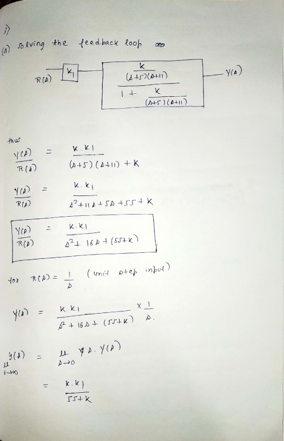
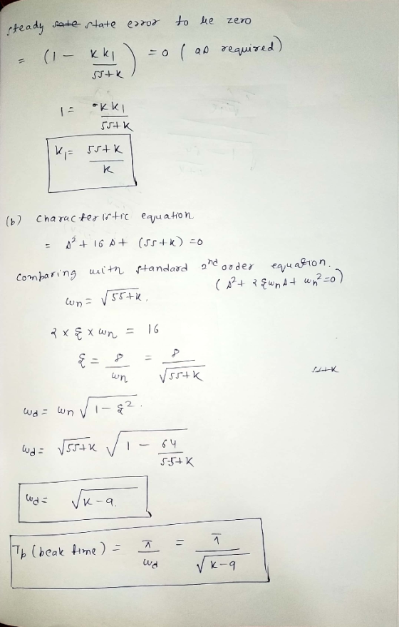
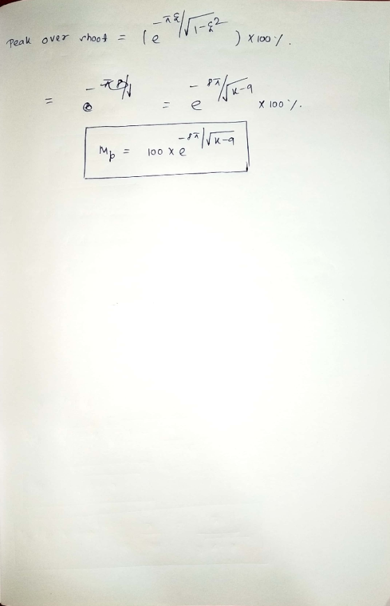
3- Consider the following system. a) b) Select Ki so that the steady state error is zero. Determi...
Consider the closed loop system defined by the following block diagram. a) Compute the transfer function...
 Consider the closed loop system defined by the following block diagram. a) Compute the transfer function E(s)/R(s). b) Determine the steady state error for a unit-step 1. Controller ant Itly Ro- +- HI- 4단Toy , c) d) e) reference input signal. Determine the steady state error response for a unit-ramp reference input signal. Determine the locations of the closed loop poles of the system. Select system parameters kp and ki in terms of k so that damping coefficient V2/2 and...
3. Consider a system with the following state equation h(t)] [0 0 21 [X1(t) [x1(t) y(t)...
 3. Consider a system with the following state equation h(t)] [0 0 21 [X1(t) [x1(t) y(t) [0.1 0 0.1x2(t) X3(t) The unit step response is required to have a settling time of less than 2 seconds and a percent overshoot of less than 5%. In addition a zero steady-state error is needed. The goal is to design the state feedback control law in the form of u(t) Kx(t) + Gr(t) (a) Find the desired regon of the S-plane for two...
A unity feedback system with the forward transfer function G(s)=K/(s+1)(s+3)(s+6) is operating wi...
 A unity feedback system with the forward transfer function
G(s)=K/(s+1)(s+3)(s+6) is operating with a closed-loop step
response that has 15% overshoot. Do the following:
a) Evaluate the steady-state error for a unit step input
b) Design a PI control to reduce the steady-state error to zero
without affecting its transient response
c) Evaluate the steady-state error and overshoot for a unit step
input to your compensated system
A unity feedback system with the forward transfer function G(s) is operating with...
A unity feedback system with the forward transfer function
G(s)=K/(s+1)(s+3)(s+6) is operating with a closed-loop step
response that has 15% overshoot. Do the following:
a) Evaluate the steady-state error for a unit step input
b) Design a PI control to reduce the steady-state error to zero
without affecting its transient response
c) Evaluate the steady-state error and overshoot for a unit step
input to your compensated system
A unity feedback system with the forward transfer function G(s) is operating with...
Problem 7.2 The differential equations for a second-order thermal system are y=x2 where u is the control input. (a) Show that the plant is type zero. As a consequence, the steady-state error using pr...
 Problem 7.2 The differential equations for a second-order thermal system are y=x2 where u is the control input. (a) Show that the plant is type zero. As a consequence, the steady-state error using proportional control is non-zero. Find the steady-state error as a function of G (b) To achieve zero steady-state error, integral control will be used, by adding the state variable zo with which is appended to the original equations, making the system third-order. For the resulting third-order system,...
5, (29%) Consider the feedback control system in Figure-5 in block diagram form. The reference input...
 5, (29%) Consider the feedback control system in Figure-5 in block diagram form. The reference input R(s), system output Y(s), and disturbance D(s) are denoted along with the error E(s) and control effort F(s). You will design the control law Gc(s) to achieve certain performance criteria. Answer the following questions (assume D(s)0 in all parts except part(ü) (a) [396] Show that the transfer function relating the reference R(s) to the output Y(s) is given by (b) [3%) Assuming a proportional...
Q1. A closed-loop transfer function is G(s) Yo.108(s+3) els> ) Determine the steady-state error f...
 Q1. A closed-loop transfer function is G(s) Yo.108(s+3) els> ) Determine the steady-state error for a unit step imput R(s)-14s Error signal is E(s) - R(s)-Y(s). Assume that the complex of the final value. ii) poles dominate and determine the overshoot and settling time to within 2%
Q1. A closed-loop transfer function is G(s) Yo.108(s+3) els> ) Determine the steady-state error for a unit step imput R(s)-14s Error signal is E(s) - R(s)-Y(s). Assume that the complex of the final...
Q1. A closed-loop transfer function is G(s) Yo.108(s+3) els> ) Determine the steady-state error for a unit step imput R(s)-14s Error signal is E(s) - R(s)-Y(s). Assume that the complex of the final value. ii) poles dominate and determine the overshoot and settling time to within 2%
Q1. A closed-loop transfer function is G(s) Yo.108(s+3) els> ) Determine the steady-state error for a unit step imput R(s)-14s Error signal is E(s) - R(s)-Y(s). Assume that the complex of the final...
Question 2 a) Consider the control system in Figure 2(a). Determine the transient response characteristics (rise...
 Question 2 a) Consider the control system in Figure 2(a). Determine the transient response characteristics (rise time, peak time, maximum overshoot and settling time) and the steady state error for the system. (2 marks) b) To improve the relative stability, the tachometer feedback are employed as shown in Figure 2b). i Determine the value in so that the damping ratio of the system is 0.5. (1 % marks) From the result obtained in , evaluate the transient response characteristics (rise...
Lag Compensator Design Using Root-Locus 2. Consider the unity feedback system in Figure 1 for G(s...
 Lag Compensator Design Using Root-Locus 2. Consider the unity feedback system in Figure 1 for G(s)- s(s+3(s6) Design a lag compensation to meet the following specifications The step response settling time is to be less than 5 sec. . The step response overshoot is to be less than 17% . The steady-state error to a unit ramp input must not exceed 10%. Dynamic specifications (overshoot and settling time) can be met using proportional feedback, but a lag compensator is needed...
help Consider the closed-loop system in Figure E5.19. where Gs)G 3s and H(s) -K (a) Determine...
 help
Consider the closed-loop system in Figure E5.19. where Gs)G 3s and H(s) -K (a) Determine the closed-loop transfer function T(s) Y(s)/R(s). (b) Determine the steady-state error of the closed-loop system response to a unit ramp input, R(s) 1/s (c) Select a value for Ka so that the steady-state error of the system response to a unit step input, R(s)1/s, is zero.
help
Consider the closed-loop system in Figure E5.19. where Gs)G 3s and H(s) -K (a) Determine the closed-loop transfer function T(s) Y(s)/R(s). (b) Determine the steady-state error of the closed-loop system response to a unit ramp input, R(s) 1/s (c) Select a value for Ka so that the steady-state error of the system response to a unit step input, R(s)1/s, is zero.
Question 2 a) Consider the control system in Figure 2(a). Determine the transient response characteristics (rise...
 Question 2 a) Consider the control system in Figure 2(a). Determine the transient response characteristics (rise time, peak time, maximum overshoot and settling time) and the steady state error for the system. (2 marks) b) To improve the relative stability, the tachometer feedback are employed as shown in Figure 2(b). Determine the value K, so that the damping ratio of the system is 0.5. (1 % marks) i. From the result obtained in (), evaluate the transient response characteristics (rise...
 Consider the closed loop system defined by the following block diagram. a) Compute the transfer function E(s)/R(s). b) Determine the steady state error for a unit-step 1. Controller ant Itly Ro- +- HI- 4단Toy , c) d) e) reference input signal. Determine the steady state error response for a unit-ramp reference input signal. Determine the locations of the closed loop poles of the system. Select system parameters kp and ki in terms of k so that damping coefficient V2/2 and...
 3. Consider a system with the following state equation h(t)] [0 0 21 [X1(t) [x1(t) y(t) [0.1 0 0.1x2(t) X3(t) The unit step response is required to have a settling time of less than 2 seconds and a percent overshoot of less than 5%. In addition a zero steady-state error is needed. The goal is to design the state feedback control law in the form of u(t) Kx(t) + Gr(t) (a) Find the desired regon of the S-plane for two...
 A unity feedback system with the forward transfer function
G(s)=K/(s+1)(s+3)(s+6) is operating with a closed-loop step
response that has 15% overshoot. Do the following:
a) Evaluate the steady-state error for a unit step input
b) Design a PI control to reduce the steady-state error to zero
without affecting its transient response
c) Evaluate the steady-state error and overshoot for a unit step
input to your compensated system
A unity feedback system with the forward transfer function G(s) is operating with...
A unity feedback system with the forward transfer function
G(s)=K/(s+1)(s+3)(s+6) is operating with a closed-loop step
response that has 15% overshoot. Do the following:
a) Evaluate the steady-state error for a unit step input
b) Design a PI control to reduce the steady-state error to zero
without affecting its transient response
c) Evaluate the steady-state error and overshoot for a unit step
input to your compensated system
A unity feedback system with the forward transfer function G(s) is operating with...
 Problem 7.2 The differential equations for a second-order thermal system are y=x2 where u is the control input. (a) Show that the plant is type zero. As a consequence, the steady-state error using proportional control is non-zero. Find the steady-state error as a function of G (b) To achieve zero steady-state error, integral control will be used, by adding the state variable zo with which is appended to the original equations, making the system third-order. For the resulting third-order system,...
 5, (29%) Consider the feedback control system in Figure-5 in block diagram form. The reference input R(s), system output Y(s), and disturbance D(s) are denoted along with the error E(s) and control effort F(s). You will design the control law Gc(s) to achieve certain performance criteria. Answer the following questions (assume D(s)0 in all parts except part(ü) (a) [396] Show that the transfer function relating the reference R(s) to the output Y(s) is given by (b) [3%) Assuming a proportional...
 Q1. A closed-loop transfer function is G(s) Yo.108(s+3) els> ) Determine the steady-state error for a unit step imput R(s)-14s Error signal is E(s) - R(s)-Y(s). Assume that the complex of the final value. ii) poles dominate and determine the overshoot and settling time to within 2%
Q1. A closed-loop transfer function is G(s) Yo.108(s+3) els> ) Determine the steady-state error for a unit step imput R(s)-14s Error signal is E(s) - R(s)-Y(s). Assume that the complex of the final...
Q1. A closed-loop transfer function is G(s) Yo.108(s+3) els> ) Determine the steady-state error for a unit step imput R(s)-14s Error signal is E(s) - R(s)-Y(s). Assume that the complex of the final value. ii) poles dominate and determine the overshoot and settling time to within 2%
Q1. A closed-loop transfer function is G(s) Yo.108(s+3) els> ) Determine the steady-state error for a unit step imput R(s)-14s Error signal is E(s) - R(s)-Y(s). Assume that the complex of the final...
 Question 2 a) Consider the control system in Figure 2(a). Determine the transient response characteristics (rise time, peak time, maximum overshoot and settling time) and the steady state error for the system. (2 marks) b) To improve the relative stability, the tachometer feedback are employed as shown in Figure 2b). i Determine the value in so that the damping ratio of the system is 0.5. (1 % marks) From the result obtained in , evaluate the transient response characteristics (rise...
 Lag Compensator Design Using Root-Locus 2. Consider the unity feedback system in Figure 1 for G(s)- s(s+3(s6) Design a lag compensation to meet the following specifications The step response settling time is to be less than 5 sec. . The step response overshoot is to be less than 17% . The steady-state error to a unit ramp input must not exceed 10%. Dynamic specifications (overshoot and settling time) can be met using proportional feedback, but a lag compensator is needed...
 help
Consider the closed-loop system in Figure E5.19. where Gs)G 3s and H(s) -K (a) Determine the closed-loop transfer function T(s) Y(s)/R(s). (b) Determine the steady-state error of the closed-loop system response to a unit ramp input, R(s) 1/s (c) Select a value for Ka so that the steady-state error of the system response to a unit step input, R(s)1/s, is zero.
help
Consider the closed-loop system in Figure E5.19. where Gs)G 3s and H(s) -K (a) Determine the closed-loop transfer function T(s) Y(s)/R(s). (b) Determine the steady-state error of the closed-loop system response to a unit ramp input, R(s) 1/s (c) Select a value for Ka so that the steady-state error of the system response to a unit step input, R(s)1/s, is zero.
 Question 2 a) Consider the control system in Figure 2(a). Determine the transient response characteristics (rise time, peak time, maximum overshoot and settling time) and the steady state error for the system. (2 marks) b) To improve the relative stability, the tachometer feedback are employed as shown in Figure 2(b). Determine the value K, so that the damping ratio of the system is 0.5. (1 % marks) i. From the result obtained in (), evaluate the transient response characteristics (rise...
Most questions answered within 3 hours.
-
Where is the error in this code sequence?
String s1 = "Hello";
String s2 = "ello";...
asked 11 months ago -
Financial data for Joel de Paris, Inc., for last year
follow:
Joel de Paris, Inc.
Balance...
asked 11 months ago -
Consider this reaction:
Al2(SO4)3 (aq)+ BaCl3
(aq) Al2Cl6 (aq)- +
3BaSO4(s) . What is the...
asked 11 months ago -
Suppose that Savneet is considering increasing her
recent random sample from 20 car rentals to 40...
asked 11 months ago -
Trucks arrive at an unloading terminal at an average rate of 120
per hour.
Trucks arrive...
asked 11 months ago -
Why are methanol and ethanol completely soluble in water while
octanol is not very little soluble....
asked 11 months ago -
A facilities manager at a university reads in a research report
that the mean amount of...
asked 11 months ago -
When the CuSO4 is rehydrated by adding water to the anhydrous
compound, is this an endothermic...
asked 11 months ago -
A ray of sunlight is passing from diamond into crown glass; the
angle of incidence is...
asked 11 months ago -
A block of mass 0.249 kg is placed on top of a light, vertical
spring of...
asked 11 months ago -
how do the kidneys compensate in the presences of acidosis
a) trigger hyperventilate
b) reserve acid...
asked 11 months ago -
Question 501 pts
The rental rate of capital to the firm increases. Which of the
following...
asked 11 months ago