
Homework Answers
Add Answer to:
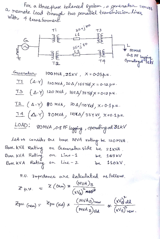
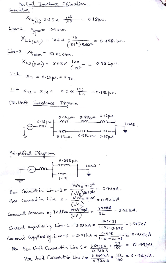
12. For a three-phase balanced system, a generator serves a remote load through two parallel tran...
QUESTION 5 a) Define the Per Unit system and list three (3) main reasons of using Per Unit system...
 Per unit calculation
QUESTION 5 a) Define the Per Unit system and list three (3) main reasons of using Per Unit systemm. (5 marks) b) A three-bus power with two generator system is shown in figure Q2 (b). The 3-phase power and line-line voltage ratings are given below Ti T2 J40 2 Gi G2 j25 Ω 25 Ω Ty Figure Q2 (b) GI: 750 MVA, 18 kV, X 7% G2: 750 MVA, 18 kV, X-15% Motor: 1500 MVA, 20 kV,...
Per unit calculation
QUESTION 5 a) Define the Per Unit system and list three (3) main reasons of using Per Unit systemm. (5 marks) b) A three-bus power with two generator system is shown in figure Q2 (b). The 3-phase power and line-line voltage ratings are given below Ti T2 J40 2 Gi G2 j25 Ω 25 Ω Ty Figure Q2 (b) GI: 750 MVA, 18 kV, X 7% G2: 750 MVA, 18 kV, X-15% Motor: 1500 MVA, 20 kV,...
1. A three-phase synchronous generator connected to a 345-KV transmission line through a transformer as shown...
 1. A three-phase synchronous generator connected to a 345-KV transmission line through a transformer as shown in Figure P1. Parameters of both generator and transformer are given in the figure. Transformer losses and exciting current are neglected. A three-phase short-circuit occurs on the line side of the circuit breaker when the generator is operated at rated terminal voltage and at no-load. The breaker interrupts the fault three cycles after fault inception. Neglect the effect of the transformer on the time...
3. A 200 MVA, 20 kV, 60 Hz Y-connected solidly grounded three phase synchronous generator connect...
 3. A 200 MVA, 20 kV, 60 Hz Y-connected solidly grounded three phase synchronous generator connected through a 200 MVA 20/138 KV Y-Y transformer to a 138 kV transmission line. The generator reactances to the machine's own base are X-1.10 Both of the transformers Y connections are solidly grounded and its positive, negative and zero sequence series resitances are all 0.10 pu. a. What is the voltage at the terminals of the generator during the sub transient period if a...
Power System
A simple three-phase power system is shown in Figure 2. Assume that the ratings of the various devices in this system are as follows: • Generators G1, G2: 40 MVA, 13.2 kV, = 0.15 pu, = 0.15 pu, = 0.08 • Generator G3: 60 MVA, 13.8 kV, = 0.20 pu, 0.20 pu, - 0.08 • Transformers T1, T2, T3, T4: 40 MVA, 13.8/138 kV, X1 = X2 = 0.10 pu, XO 0.08 pu Transformers T5, T6: 30 MVA, 13.8/138 kV, X1 = X2...
The three-phase power and line-line ratings of the electric power system shown in Figure 2 are...
 The three-phase power and line-line ratings of the electric power system shown in Figure 2 are given below. T1 T2 V. 1 2 vm 9 Line G M Figure 2 One-line diagram for problem 2 G: T1: 60 MVA 50 MVA 50 MVA T2: Line: M: 20 kV 20/200 kV 200/20 kV 200 kV 18 kV X=9% X=10% X=10% Z=120+j200 12 X=8% 43.2 MVA (a) Draw an impedance diagram showing all impedances in per unit on a 100-MVA base. Choose...
Problem #1 Part I (50 points) Consider the following one-line diagram of a three-phase power system. Assume that the system has the following base quantities: S3 100 MVA, and VbaselL 38 kV at the...
 Problem #1 Part I (50 points) Consider the following one-line diagram of a three-phase power system. Assume that the system has the following base quantities: S3 100 MVA, and VbaselL 38 kV at the generator side. The rated line-to-line terminal voltage of the generator (BUS 1) is 38 kV. A single-circuit three-phase transposed overhead line composed by one ACSR Partridge conductor per phase with vertical configuration. The transmission line length is 50 km and the distance between phases a-b, b-c...
Fig Qshows the one-line diagram of a three-phase power system. As shown in Fig. Q3. the...
 Fig Qshows the one-line diagram of a three-phase power system.
As shown in Fig. Q3. the two zones are connected by a 400 MVA,
240-kV/24-kV, Ý-A three phase transformer. The Y-A three phase
transfonmer has an equivalent series impedance of ZTH - 1.2 + j1.6n
per phase referred to the high voltage side (primary side). The
three-phase power system can be studied with per unit quantities
using base values of S-500 MVA and 240 kV in zone 1.
By using...
Fig Qshows the one-line diagram of a three-phase power system.
As shown in Fig. Q3. the two zones are connected by a 400 MVA,
240-kV/24-kV, Ý-A three phase transformer. The Y-A three phase
transfonmer has an equivalent series impedance of ZTH - 1.2 + j1.6n
per phase referred to the high voltage side (primary side). The
three-phase power system can be studied with per unit quantities
using base values of S-500 MVA and 240 kV in zone 1.
By using...
3. A balanced three-phase delta connected load with 15+j10 ohms load on each balanced, wye connected...
 3. A balanced three-phase delta connected load with 15+j10 ohms load on each balanced, wye connected source with Van branch is supplied by a -7.6240 KV, while the transmission line impedances are 1+7j on each line. Calculate the line currents (currents on the transmission lines) la, 1b, and 1c. (Hint: convert the Δ configured load into a Y configured load
Please show me step by step how to get load impedance in per-unit. New load is 1.05+1.4j per unit...
 Please show me step by step how to get load impedance in
per-unit. New load is 1.05+1.4j per unit and new z load is 0.447
per unit
Consider the three-phase power system in the figure below. By selecting a common base of 100 MVA and 22 kV on the generator side, draw an impedance diagram showing all impedances, including the load impedance in per-unit. Lines 1 and 2 have series reactances of 48.4 and 65.43 2, respectively. At bus 4,...
Please show me step by step how to get load impedance in
per-unit. New load is 1.05+1.4j per unit and new z load is 0.447
per unit
Consider the three-phase power system in the figure below. By selecting a common base of 100 MVA and 22 kV on the generator side, draw an impedance diagram showing all impedances, including the load impedance in per-unit. Lines 1 and 2 have series reactances of 48.4 and 65.43 2, respectively. At bus 4,...
can you calculating this question and explain why? thanks The ratings and sequence reactances of the components for...
 can you calculating this question and explain why?
thanks
The ratings and sequence reactances of the components for the power system shown in Figure 2 are given in Table 1. The pre-fault voltage is 1/0° per unit (pu). Bus 8 L3 Bus 1 T1 Bus 4 T2 Bus 2 Bus 5 L1 L2 G1 Bus 3 T3 Bus 7 Bus 6 D.6975 Figure Draw the per unit impedance sequence networks and determine the per unit (a) Thevenin impedances of the...
can you calculating this question and explain why?
thanks
The ratings and sequence reactances of the components for the power system shown in Figure 2 are given in Table 1. The pre-fault voltage is 1/0° per unit (pu). Bus 8 L3 Bus 1 T1 Bus 4 T2 Bus 2 Bus 5 L1 L2 G1 Bus 3 T3 Bus 7 Bus 6 D.6975 Figure Draw the per unit impedance sequence networks and determine the per unit (a) Thevenin impedances of the...
 Per unit calculation
QUESTION 5 a) Define the Per Unit system and list three (3) main reasons of using Per Unit systemm. (5 marks) b) A three-bus power with two generator system is shown in figure Q2 (b). The 3-phase power and line-line voltage ratings are given below Ti T2 J40 2 Gi G2 j25 Ω 25 Ω Ty Figure Q2 (b) GI: 750 MVA, 18 kV, X 7% G2: 750 MVA, 18 kV, X-15% Motor: 1500 MVA, 20 kV,...
Per unit calculation
QUESTION 5 a) Define the Per Unit system and list three (3) main reasons of using Per Unit systemm. (5 marks) b) A three-bus power with two generator system is shown in figure Q2 (b). The 3-phase power and line-line voltage ratings are given below Ti T2 J40 2 Gi G2 j25 Ω 25 Ω Ty Figure Q2 (b) GI: 750 MVA, 18 kV, X 7% G2: 750 MVA, 18 kV, X-15% Motor: 1500 MVA, 20 kV,...
 1. A three-phase synchronous generator connected to a 345-KV transmission line through a transformer as shown in Figure P1. Parameters of both generator and transformer are given in the figure. Transformer losses and exciting current are neglected. A three-phase short-circuit occurs on the line side of the circuit breaker when the generator is operated at rated terminal voltage and at no-load. The breaker interrupts the fault three cycles after fault inception. Neglect the effect of the transformer on the time...
 3. A 200 MVA, 20 kV, 60 Hz Y-connected solidly grounded three phase synchronous generator connected through a 200 MVA 20/138 KV Y-Y transformer to a 138 kV transmission line. The generator reactances to the machine's own base are X-1.10 Both of the transformers Y connections are solidly grounded and its positive, negative and zero sequence series resitances are all 0.10 pu. a. What is the voltage at the terminals of the generator during the sub transient period if a...
 The three-phase power and line-line ratings of the electric power system shown in Figure 2 are given below. T1 T2 V. 1 2 vm 9 Line G M Figure 2 One-line diagram for problem 2 G: T1: 60 MVA 50 MVA 50 MVA T2: Line: M: 20 kV 20/200 kV 200/20 kV 200 kV 18 kV X=9% X=10% X=10% Z=120+j200 12 X=8% 43.2 MVA (a) Draw an impedance diagram showing all impedances in per unit on a 100-MVA base. Choose...
 Problem #1 Part I (50 points) Consider the following one-line diagram of a three-phase power system. Assume that the system has the following base quantities: S3 100 MVA, and VbaselL 38 kV at the generator side. The rated line-to-line terminal voltage of the generator (BUS 1) is 38 kV. A single-circuit three-phase transposed overhead line composed by one ACSR Partridge conductor per phase with vertical configuration. The transmission line length is 50 km and the distance between phases a-b, b-c...
 Fig Qshows the one-line diagram of a three-phase power system.
As shown in Fig. Q3. the two zones are connected by a 400 MVA,
240-kV/24-kV, Ý-A three phase transformer. The Y-A three phase
transfonmer has an equivalent series impedance of ZTH - 1.2 + j1.6n
per phase referred to the high voltage side (primary side). The
three-phase power system can be studied with per unit quantities
using base values of S-500 MVA and 240 kV in zone 1.
By using...
Fig Qshows the one-line diagram of a three-phase power system.
As shown in Fig. Q3. the two zones are connected by a 400 MVA,
240-kV/24-kV, Ý-A three phase transformer. The Y-A three phase
transfonmer has an equivalent series impedance of ZTH - 1.2 + j1.6n
per phase referred to the high voltage side (primary side). The
three-phase power system can be studied with per unit quantities
using base values of S-500 MVA and 240 kV in zone 1.
By using...
 3. A balanced three-phase delta connected load with 15+j10 ohms load on each balanced, wye connected source with Van branch is supplied by a -7.6240 KV, while the transmission line impedances are 1+7j on each line. Calculate the line currents (currents on the transmission lines) la, 1b, and 1c. (Hint: convert the Δ configured load into a Y configured load
 Please show me step by step how to get load impedance in
per-unit. New load is 1.05+1.4j per unit and new z load is 0.447
per unit
Consider the three-phase power system in the figure below. By selecting a common base of 100 MVA and 22 kV on the generator side, draw an impedance diagram showing all impedances, including the load impedance in per-unit. Lines 1 and 2 have series reactances of 48.4 and 65.43 2, respectively. At bus 4,...
Please show me step by step how to get load impedance in
per-unit. New load is 1.05+1.4j per unit and new z load is 0.447
per unit
Consider the three-phase power system in the figure below. By selecting a common base of 100 MVA and 22 kV on the generator side, draw an impedance diagram showing all impedances, including the load impedance in per-unit. Lines 1 and 2 have series reactances of 48.4 and 65.43 2, respectively. At bus 4,...
 can you calculating this question and explain why?
thanks
The ratings and sequence reactances of the components for the power system shown in Figure 2 are given in Table 1. The pre-fault voltage is 1/0° per unit (pu). Bus 8 L3 Bus 1 T1 Bus 4 T2 Bus 2 Bus 5 L1 L2 G1 Bus 3 T3 Bus 7 Bus 6 D.6975 Figure Draw the per unit impedance sequence networks and determine the per unit (a) Thevenin impedances of the...
can you calculating this question and explain why?
thanks
The ratings and sequence reactances of the components for the power system shown in Figure 2 are given in Table 1. The pre-fault voltage is 1/0° per unit (pu). Bus 8 L3 Bus 1 T1 Bus 4 T2 Bus 2 Bus 5 L1 L2 G1 Bus 3 T3 Bus 7 Bus 6 D.6975 Figure Draw the per unit impedance sequence networks and determine the per unit (a) Thevenin impedances of the...
Most questions answered within 3 hours.
-
Where is the error in this code sequence?
String s1 = "Hello";
String s2 = "ello";...
asked 11 months ago -
Financial data for Joel de Paris, Inc., for last year
follow:
Joel de Paris, Inc.
Balance...
asked 11 months ago -
Consider this reaction:
Al2(SO4)3 (aq)+ BaCl3
(aq) Al2Cl6 (aq)- +
3BaSO4(s) . What is the...
asked 11 months ago -
Suppose that Savneet is considering increasing her
recent random sample from 20 car rentals to 40...
asked 11 months ago -
Trucks arrive at an unloading terminal at an average rate of 120
per hour.
Trucks arrive...
asked 11 months ago -
Why are methanol and ethanol completely soluble in water while
octanol is not very little soluble....
asked 11 months ago -
A facilities manager at a university reads in a research report
that the mean amount of...
asked 11 months ago -
When the CuSO4 is rehydrated by adding water to the anhydrous
compound, is this an endothermic...
asked 11 months ago -
A ray of sunlight is passing from diamond into crown glass; the
angle of incidence is...
asked 11 months ago -
A block of mass 0.249 kg is placed on top of a light, vertical
spring of...
asked 11 months ago -
how do the kidneys compensate in the presences of acidosis
a) trigger hyperventilate
b) reserve acid...
asked 11 months ago -
Question 501 pts
The rental rate of capital to the firm increases. Which of the
following...
asked 11 months ago