
Homework Answers
Add Answer to:
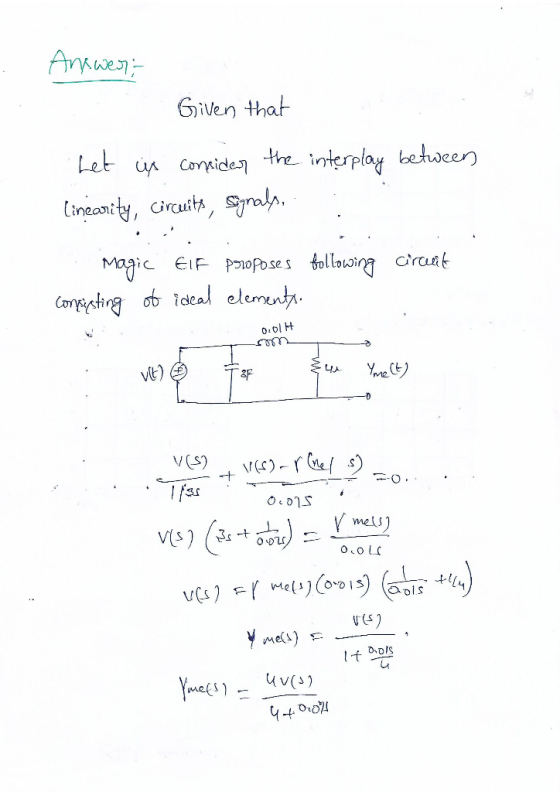
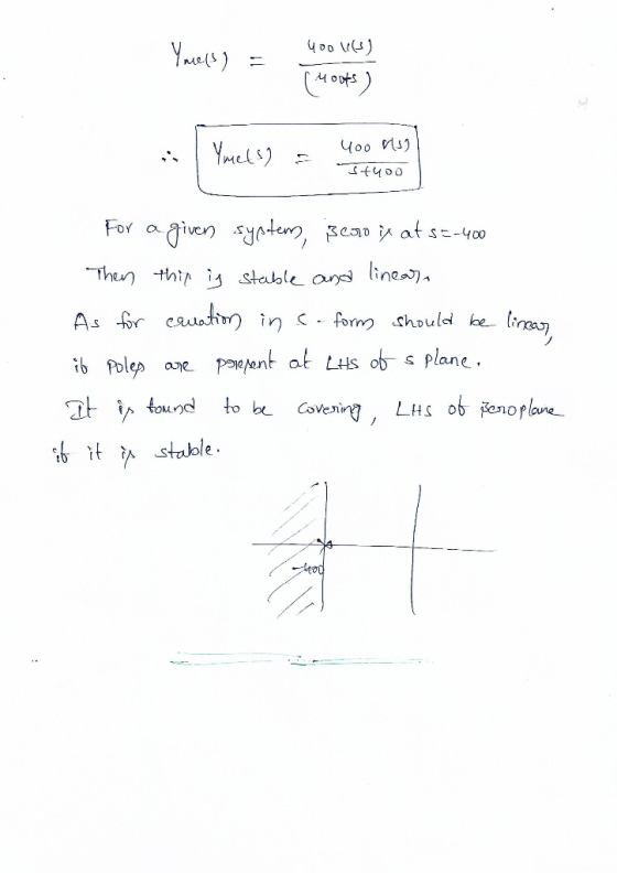
Ucosderthe interbeween iearit and igna A Magic Elf proposes the following following circuit consi...
An engineer wants to design a circuit that has the following input/output voltage characteristics. The variable...
 An engineer wants to design a circuit that has the following input/output voltage characteristics. The variable input DC voltage source that the engineer uses has 0.5 kOhm internal resistance; in the laboratory various diodes (pn and Zener), resistors and various fixed DC voltages are available. The diodes cannot be assumed as "ideal" in the design. Sketch your circuit, show all your calculations, mathematical validations and give specifications of your selected circuit elements with their values [40]. Vout (V) 3 2...
2-a)-RLC components connected in series in a circuit supplied by a variable dc voltage can be described by the following differential equations: di(t) wherei@ is the loop current and V1(t) İs the vol...
 2-a)-RLC components connected in series in a circuit supplied by a variable dc voltage can be described by the following differential equations: di(t) wherei@ is the loop current and V1(t) İs the voltage drop across the inductor.+' The voltage drop across the resistor is given by Ohm's law vR(t) R i(t) and the voltage drop across the capacitor vc(t) is given by i(t) dt For a series circuit ye)t vit)t velt) v(t) where v(t) is applied voltage: Figure 3: RLC...
The switch in an effective LR series dc-circuit (consisting of an emf and a coil with...
 The switch in an effective LR series dc-circuit (consisting of an emf and a coil with inductance L = 0.5 H and unknown internal resistance) is closed at t = 0 sec. At t = r, the current is 9.5 A and is increasing at a rate of 1.1 A/s. What must the internal resistance of the coil be? A step-up transformer is designed to have an output voltage of 1800 V (rms) when the primary is connect across a...
02 +Vo D3 Rgare 18 Circuit for Problem 1 Analysis 1. Copy the circuit of Figure 1.8 and sketch the ow of pesitive curment throughout the entire circuit for o>0. Repeat for n ce 2....
 02 +Vo D3 Rgare 18 Circuit for Problem 1 Analysis 1. Copy the circuit of Figure 1.8 and sketch the ow of pesitive curment throughout the entire circuit for o>0. Repeat for n ce 2. Plot two periods of nlt) and s) for each of the thee input wave shown in Figune 17 on page 37 fom output t (a) Feak value, and b) Eflective DC value, also known as RMS value NotTE These and are therefore optional 4. Determine...
nde) Figare 18 Circuit for Problem 15 Analysis 1. Plot the input and output vollage wavefoems nlt) and lt) as wel as the capacitor current iclt) for the input wavelorm shown in Fig ure 1....
 nde) Figare 18 Circuit for Problem 15 Analysis 1. Plot the input and output vollage wavefoems nlt) and lt) as wel as the capacitor current iclt) for the input wavelorm shown in Fig ure 1.10 on the next page, Assume the capacitoris initially discharged 2 Determine the following numerical descriptors for lf) and iclf (a) Voltage values of t) at times-250, 650, and 960ms. (b) Peak capacitor current t Discass the relationship between the plots of the capacitor current ic(t)...
te=300 H 7 #2 Zoov 32.- 12 yol A Series Circuit Consisting of a 43. A...
 te=300 H 7 #2 Zoov 32.- 12 yol A Series Circuit Consisting of a 43. A Series RLC Circuit R=4252, 1#4 100 32 novinke five resisfor, a coil In a purely inductive AC L=125H and C= 3.0. I Circuit, L = 250mH and the rms with a 0.10H and a 20 uf Capacitor Constad to an Ac Source with Voltage of 1500. across a llov, CH2 power Source (f = 60.042 and Vmax = 150V Calculate the inductive Reactance @...
A MOSFET and diode is used in a circuit shown in figure. The operating conditions are...
A MOSFET and diode is used in a circuit shown in figure. The operating conditions are as follows: Input Voltage = VIN = 42 V, Io = 5A. Switching frequency fs = 400 kHz, Duty-cycle = D = 0.3. Diode Forward Voltage drop = 0.7V. Diode Peak Reverse Recovery Current = IRRM = 2.5 A. ON-state resistance of the MOSFET is RDS (on) = 25 mΩ. VGG as a step voltage between 0V and 10 V. MOSFET timings – Td...
A triangular waveform voltage (shown below to the right) is applied to the following circuit input...
 A triangular waveform voltage (shown below to the right) is
applied to the following circuit input terminals. The circuit’s
value of C is 200 nano-farad and the value of R is 47 kilo-ohm. The
output voltage is measured with a high impedance A-to-D converter.
Recalling that such a passive element circuit is a linear-time
invariant system which can be solved with superposition
principles:
a) Determine eout at time = 1.5 milli-second.
b) Determine the time when there is no current...
A triangular waveform voltage (shown below to the right) is
applied to the following circuit input terminals. The circuit’s
value of C is 200 nano-farad and the value of R is 47 kilo-ohm. The
output voltage is measured with a high impedance A-to-D converter.
Recalling that such a passive element circuit is a linear-time
invariant system which can be solved with superposition
principles:
a) Determine eout at time = 1.5 milli-second.
b) Determine the time when there is no current...
Problems,,,,,
 1 2
+
–
i(t)
C R
L
iT i(t)
iD
+
–
L C R
1. Analysis and design of a buck-boost converter: A buck-boost converter is illustrated in Fig. 1(a),
and a practical implementation using a transistor and diode is shown in Fig. 1(b).
+
(a)
Vg
v
Figure 1 Buck–boost converter
of Problem 1: (a) ideal converter
circuit, (b) implementation using
MOSFET and diode.
–
Q1
D1
(b) +
Vg
v
Page 2
iL
(t) + vL...
1 2
+
–
i(t)
C R
L
iT i(t)
iD
+
–
L C R
1. Analysis and design of a buck-boost converter: A buck-boost converter is illustrated in Fig. 1(a),
and a practical implementation using a transistor and diode is shown in Fig. 1(b).
+
(a)
Vg
v
Figure 1 Buck–boost converter
of Problem 1: (a) ideal converter
circuit, (b) implementation using
MOSFET and diode.
–
Q1
D1
(b) +
Vg
v
Page 2
iL
(t) + vL...
6. LED Alarm Circuit One day, you come back to your dorm to find that your...
 6. LED Alarm Circuit One day, you come back to your dorm to find that your favorite candy has been stolen. Determined to catch the perpetrator red-handed, you decide to put the candy inside a kitchen drawer. Using the following circuit design, you would like to turn on a light-emitting diode (LED) "alarm" if the kitchen drawer is opened. Rli LED 2.5V LED Note Rphoto is a photoresistor, which acts like a typical resistor but changes resistance based on the...
 An engineer wants to design a circuit that has the following input/output voltage characteristics. The variable input DC voltage source that the engineer uses has 0.5 kOhm internal resistance; in the laboratory various diodes (pn and Zener), resistors and various fixed DC voltages are available. The diodes cannot be assumed as "ideal" in the design. Sketch your circuit, show all your calculations, mathematical validations and give specifications of your selected circuit elements with their values [40]. Vout (V) 3 2...
 2-a)-RLC components connected in series in a circuit supplied by a variable dc voltage can be described by the following differential equations: di(t) wherei@ is the loop current and V1(t) İs the voltage drop across the inductor.+' The voltage drop across the resistor is given by Ohm's law vR(t) R i(t) and the voltage drop across the capacitor vc(t) is given by i(t) dt For a series circuit ye)t vit)t velt) v(t) where v(t) is applied voltage: Figure 3: RLC...
 The switch in an effective LR series dc-circuit (consisting of an emf and a coil with inductance L = 0.5 H and unknown internal resistance) is closed at t = 0 sec. At t = r, the current is 9.5 A and is increasing at a rate of 1.1 A/s. What must the internal resistance of the coil be? A step-up transformer is designed to have an output voltage of 1800 V (rms) when the primary is connect across a...
 02 +Vo D3 Rgare 18 Circuit for Problem 1 Analysis 1. Copy the circuit of Figure 1.8 and sketch the ow of pesitive curment throughout the entire circuit for o>0. Repeat for n ce 2. Plot two periods of nlt) and s) for each of the thee input wave shown in Figune 17 on page 37 fom output t (a) Feak value, and b) Eflective DC value, also known as RMS value NotTE These and are therefore optional 4. Determine...
 nde) Figare 18 Circuit for Problem 15 Analysis 1. Plot the input and output vollage wavefoems nlt) and lt) as wel as the capacitor current iclt) for the input wavelorm shown in Fig ure 1.10 on the next page, Assume the capacitoris initially discharged 2 Determine the following numerical descriptors for lf) and iclf (a) Voltage values of t) at times-250, 650, and 960ms. (b) Peak capacitor current t Discass the relationship between the plots of the capacitor current ic(t)...
 te=300 H 7 #2 Zoov 32.- 12 yol A Series Circuit Consisting of a 43. A Series RLC Circuit R=4252, 1#4 100 32 novinke five resisfor, a coil In a purely inductive AC L=125H and C= 3.0. I Circuit, L = 250mH and the rms with a 0.10H and a 20 uf Capacitor Constad to an Ac Source with Voltage of 1500. across a llov, CH2 power Source (f = 60.042 and Vmax = 150V Calculate the inductive Reactance @...
 A triangular waveform voltage (shown below to the right) is
applied to the following circuit input terminals. The circuit’s
value of C is 200 nano-farad and the value of R is 47 kilo-ohm. The
output voltage is measured with a high impedance A-to-D converter.
Recalling that such a passive element circuit is a linear-time
invariant system which can be solved with superposition
principles:
a) Determine eout at time = 1.5 milli-second.
b) Determine the time when there is no current...
A triangular waveform voltage (shown below to the right) is
applied to the following circuit input terminals. The circuit’s
value of C is 200 nano-farad and the value of R is 47 kilo-ohm. The
output voltage is measured with a high impedance A-to-D converter.
Recalling that such a passive element circuit is a linear-time
invariant system which can be solved with superposition
principles:
a) Determine eout at time = 1.5 milli-second.
b) Determine the time when there is no current...
 6. LED Alarm Circuit One day, you come back to your dorm to find that your favorite candy has been stolen. Determined to catch the perpetrator red-handed, you decide to put the candy inside a kitchen drawer. Using the following circuit design, you would like to turn on a light-emitting diode (LED) "alarm" if the kitchen drawer is opened. Rli LED 2.5V LED Note Rphoto is a photoresistor, which acts like a typical resistor but changes resistance based on the...
Most questions answered within 3 hours.
-
Where is the error in this code sequence?
String s1 = "Hello";
String s2 = "ello";...
asked 11 months ago -
Financial data for Joel de Paris, Inc., for last year
follow:
Joel de Paris, Inc.
Balance...
asked 11 months ago -
Consider this reaction:
Al2(SO4)3 (aq)+ BaCl3
(aq) Al2Cl6 (aq)- +
3BaSO4(s) . What is the...
asked 11 months ago -
Suppose that Savneet is considering increasing her
recent random sample from 20 car rentals to 40...
asked 11 months ago -
Trucks arrive at an unloading terminal at an average rate of 120
per hour.
Trucks arrive...
asked 11 months ago -
Why are methanol and ethanol completely soluble in water while
octanol is not very little soluble....
asked 11 months ago -
A facilities manager at a university reads in a research report
that the mean amount of...
asked 11 months ago -
When the CuSO4 is rehydrated by adding water to the anhydrous
compound, is this an endothermic...
asked 11 months ago -
A ray of sunlight is passing from diamond into crown glass; the
angle of incidence is...
asked 11 months ago -
A block of mass 0.249 kg is placed on top of a light, vertical
spring of...
asked 11 months ago -
how do the kidneys compensate in the presences of acidosis
a) trigger hyperventilate
b) reserve acid...
asked 11 months ago -
Question 501 pts
The rental rate of capital to the firm increases. Which of the
following...
asked 11 months ago