
Homework Answers
Boost converter:
1)
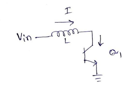
When the switch (Q1) is on, the current starts flowing from supply to ground through inductor and switch. This current starts increasing as v=Ldi/dt is the rule for the inductor and input voltage is applied across the inductor
2)
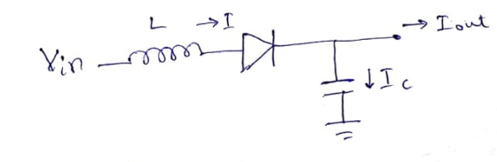
When the switch turns off, the inductor current cannot die out instantaneously. The inductor current starts decreaseing and the current flows from input to output through the diode and the inductor.
3) When the duty cycle increases, the output voltage increases. The voltage and duty ratio for a boost converter are related by the equation, Vout=Vin/(1-d).
4)As R2 increases, the output voltage increases. The duty ratio is also increased. The reason is, the control system used here is voltage mode control. i.e.; compare the scaled version of the output voltage to a reference voltage and change the duty cycle until these voltages are matched. When R2 is increased, the potential divided output voltage which is Vout*(R1/(R1+R1)) comes down. The duty ratio increases until this voltage increases to becomes equal to the reference voltage.
5) As L increases, the variation in inductor current becomes low. i.e.; the ripple in the inductor current reduces and at larger inductance values, the inductor current can almost reach a constant state. This doesn't have any effect on the output voltage though. If the inductor value is reduced very much, the inductor current will reach zero during the off period of the switch and this leads to Discontinuous operating mode of the converter.
6) CT is the timing capacitor that generates the clock signal for timing for switching the transistors. As Ct increases, the time taken by it to charge to a particuar level increases. So the switching frequency reduces. This requires larger inductors to maintain the circuit in continuous operation mode. Also the size of the capacitors for the same output ripple specification also increases. if the capacitor size is not increased, the output peak to peak ripple voltage increases.
BUCK:
1)
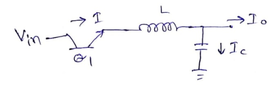
When the switch is on, the current passes through swtich and indutor into the output capacitor and load.
2)
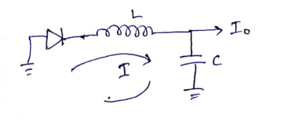
When the switch is off, the inductor current which was increasing during the switch was on, starts decreasing slowly. But the current needs some path to flow. the diode becomes forward biased and provides a path for the current.
3)
The relation for buck converter is Vout=d*Vin. As the duty ratio increases, the output voltage also increases.
4) As explained above, as d increases, the output voltage increases and so when R2 is increased, the output voltage needs to increase to a larger value so that the scaled-down value of the output equals the reference voltage.
5)As L increases, the peak to peak ripple in the inductor current is reduced and so as this ripple current passing through the capacitor produces the output voltage ripple, the output voltage ripple is also reduced
6)
As Ct increases, the frequency of switching reduces and so the ripple voltages and currents are increased. If the ripples go beyond a particular range, the system goes to discontinuous mode.
Add Answer to:
220 HH Boost circuit: 1. Draw a (simplified) schematic that shows 180 Ω how current flows when Q1...
Most questions answered within 3 hours.
-
Where is the error in this code sequence?
String s1 = "Hello";
String s2 = "ello";...
asked 11 months ago -
Financial data for Joel de Paris, Inc., for last year
follow:
Joel de Paris, Inc.
Balance...
asked 11 months ago -
Consider this reaction:
Al2(SO4)3 (aq)+ BaCl3
(aq) Al2Cl6 (aq)- +
3BaSO4(s) . What is the...
asked 11 months ago -
Suppose that Savneet is considering increasing her
recent random sample from 20 car rentals to 40...
asked 11 months ago -
Trucks arrive at an unloading terminal at an average rate of 120
per hour.
Trucks arrive...
asked 11 months ago -
Why are methanol and ethanol completely soluble in water while
octanol is not very little soluble....
asked 11 months ago -
A facilities manager at a university reads in a research report
that the mean amount of...
asked 11 months ago -
When the CuSO4 is rehydrated by adding water to the anhydrous
compound, is this an endothermic...
asked 11 months ago -
A ray of sunlight is passing from diamond into crown glass; the
angle of incidence is...
asked 11 months ago -
A block of mass 0.249 kg is placed on top of a light, vertical
spring of...
asked 11 months ago -
how do the kidneys compensate in the presences of acidosis
a) trigger hyperventilate
b) reserve acid...
asked 11 months ago -
Question 501 pts
The rental rate of capital to the firm increases. Which of the
following...
asked 11 months ago