
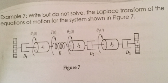

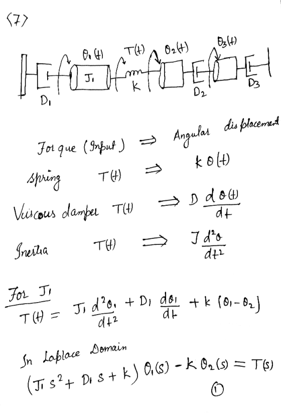
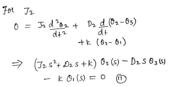
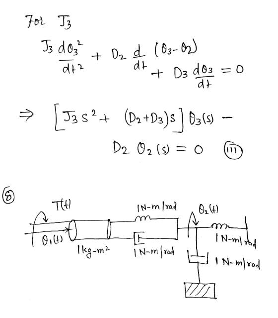
Example 7: Write but do not solve, the Laplace transform of the equations of motion for the system shown in Figure 7. 6,(t) Di D2 D3 Figure 7
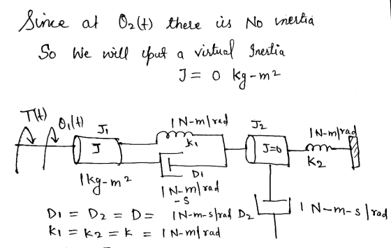
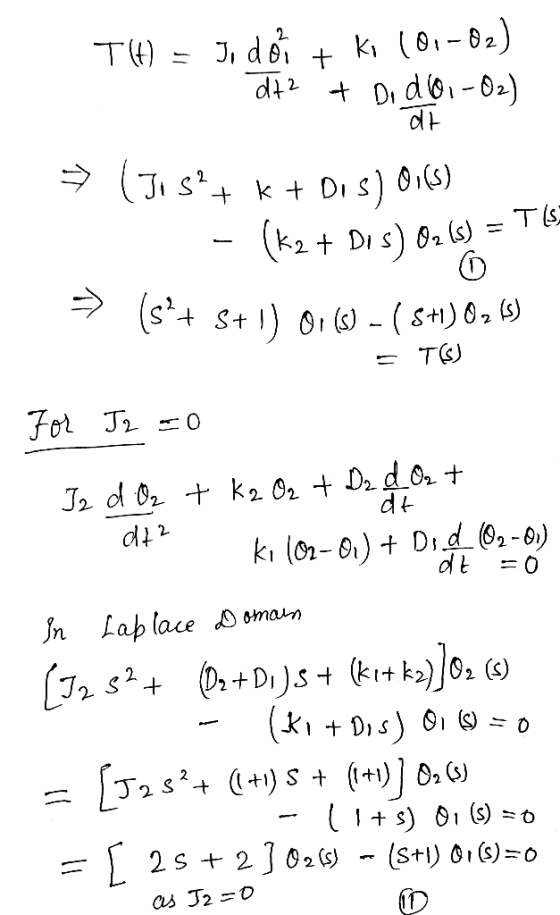
Example 8: Find the transfer function, θ2(s)/T(s), for the rotational mechanical system shown in Figure 8. 1 N-m/rad θ2(1) Tu) I N-m/rad 1 N-m-s/racd I N-m-s/rad Figure 8 /2019 ВЕКС 3533 Introduction to Control Systems
Homework Answers


Add Answer to:
Example 5a: Write, but do not solve the equations of motion for the mechanical network of Figure ...
θ2(s)/T(s) for the following rotational mechanical system Problem 4: Find the transfer function G(s) TO) N1...
 θ2(s)/T(s) for the following rotational mechanical system Problem 4: Find the transfer function G(s) TO) N1 = 4 Di 1 N-m-s/rad N2 121 kg-m2 N3-4 D2-2 N-m-s/rad K 64 N-m/rad- N4 16 D3 32 N-m-s/rad -16 kg-m2 000
Q2 A rotational mechanical system is shown in Figure 2.1. T(t) is the external torque and...
 Q2 A rotational mechanical system is shown in Figure 2.1. T(t) is the external torque and is the input to the system. 01(t) is the angular displacement of inertia Ji and O2(t) is the angular displacement of inertia J2. C and C are friction coefficients and K, and K2 are spring constants. (a) Draw the free-body diagrams for J; and Jz. (7 marks) (b) Derive the equations of motion for the system shown in Figure 2.1. (8 marks) (c) Using...
For the system shown in Fig. 1, solve the following problems. (a) Find the transfer function, G(s...
 For the system shown in Fig. 1, solve the following problems. (a) Find the transfer function, G(s)X2 (s)/F(s) (b) Does the system oscillate with a unit step input (f (t))? Explain the reason (c) Decide if the system(x2 (t)) is stable with a unit step input (f (t))? Explain the reason 1. 320) 8 kg 2 N/m 4N-s/m 2N-s/m Fig. 1 2. There are two suspensions for a car as shown in Fig. 2 (a) Find the equations of each...
Question 3) Consider the mechanical system shown in figure, T(t) is the torque applied to shaft...
 Question 3) Consider the mechanical system shown in figure, T(t) is the torque applied to shaft 1 and z(t) is the rotation of shaft 2. J.Jz and Jz are the inertias of shafts 1,2 and 3 respectively, N,,N,N, and N, are the number of teeths of the gears,, D1, D, and D3 are the coefficient of viscous damping associated with shafts 1, 2 and 3 respectively, K is the spring constant of the torsional spring attached to shaft 3. Write...
The equations of motion for a certain mechanical system with two degrees of freedom, can be...
 The equations of motion for a certain mechanical system with two degrees of freedom, can be written as a pair of coupled, second-order, differential equations: (M + m)x - 1/2 mL theta^2 sin(theta) + 1/2 mL theta cos(theta) + k(x - L_0) = 0 1/3 mL^2 theta + 1/2 mLx cos(theta) + 1/2 mgLsin(theta) = 0 We can rewrite them in matrix form, A*qdd - b, to be solved simultaneously: [M + m 1/2 mL cos theta 1/2 mL cos...
Q5 The equation of the motion of the mechanical system shown in the following figure is...
 Q5 The equation of the motion of the mechanical system shown in the following figure is governed by the following differential equation d2 x dx m7+9+= -f(t) - 3kx dt2 dt where m, C and k are mass, damping coefficient and spring constant, respectively. Consider the system with m = 10 kg, c = 80 Ns/m, k = 50 N/m, and the system is at rest at time t = 0 s. f(t) is the external force acting on the...
The mechanical system shown in the figure below is excited by a sinusoidal force f(t)-Fi cos(ut...
 The mechanical system shown in the figure below is excited by a sinusoidal force f(t)-Fi cos(ut + ?) N. The differential equation of the displacement x(t) is Use phasor techniques to solve for the displacement phasor Xin terms of the excitation frequency ? , and the mechanical elements M = 0.1 kg, D = 8 N-s/m , and K = 2,000 N/m . If Fi-10 N and ?? = 30°, determine the excitation frequency w (in rad/s) at which the...
Equations of Motion: Rectangular Coordinates a,--150 m Learning Goal To set up and solve the equations...
 Equations of Motion: Rectangular Coordinates a,--150 m Learning Goal To set up and solve the equations of motion using rectangular coordinates The 2kg collar shown has a coeficient of kinesic friction Correct = 0.2 wit, the shut The spring is urstre ed aren s :0 and the collar is given an initial velocity of to 19.6 m/s The unstretohed length of the spring is d-1.1 m and the spring constant is 423 N/m part C . The speed of the...
Solve a,b and c The vibratory movement of the engineering system shown in Figure 3 can...
 Solve a,b and c
The vibratory movement of the engineering system shown in Figure 3 can be described by two generalised coordinates, x, a Cartesian coordinate, and 6, a polar coordinate systems. The mass m and its mass moment of inertia about an axis that goes through its centre of gravity G is J. When the system is slightly pushed down from the top comer at the right hand edge of mass m, the induced vibrational motion is found to...
Solve a,b and c
The vibratory movement of the engineering system shown in Figure 3 can be described by two generalised coordinates, x, a Cartesian coordinate, and 6, a polar coordinate systems. The mass m and its mass moment of inertia about an axis that goes through its centre of gravity G is J. When the system is slightly pushed down from the top comer at the right hand edge of mass m, the induced vibrational motion is found to...
MEMB343 MECHANICAL VIBRATIONS ASSIGNMENT l. For the system shown in Figure 1, where mi=5 kg, m,-10 kg, ki=1000 N/m, k2-500 N/m, k, 2000 N/m, fi-100sin(15t) N and f-0, use modal analysis to determine...
 MEMB343 MECHANICAL VIBRATIONS ASSIGNMENT l. For the system shown in Figure 1, where mi=5 kg, m,-10 kg, ki=1000 N/m, k2-500 N/m, k, 2000 N/m, fi-100sin(15t) N and f-0, use modal analysis to determine the amplitudes of masses m, and m2. The equations of motion are given as sin(15t), wth natura frequencies 5 01[i, 0 10 500-500x, 500 2500jx, x,[100 ω,-14.14 rad's and a, = 18.71 rad/s, and mode shapes, Φ',, and Φ' k, Im Figure 1
MEMB343 MECHANICAL VIBRATIONS ASSIGNMENT...
MEMB343 MECHANICAL VIBRATIONS ASSIGNMENT l. For the system shown in Figure 1, where mi=5 kg, m,-10 kg, ki=1000 N/m, k2-500 N/m, k, 2000 N/m, fi-100sin(15t) N and f-0, use modal analysis to determine the amplitudes of masses m, and m2. The equations of motion are given as sin(15t), wth natura frequencies 5 01[i, 0 10 500-500x, 500 2500jx, x,[100 ω,-14.14 rad's and a, = 18.71 rad/s, and mode shapes, Φ',, and Φ' k, Im Figure 1
MEMB343 MECHANICAL VIBRATIONS ASSIGNMENT...
 θ2(s)/T(s) for the following rotational mechanical system Problem 4: Find the transfer function G(s) TO) N1 = 4 Di 1 N-m-s/rad N2 121 kg-m2 N3-4 D2-2 N-m-s/rad K 64 N-m/rad- N4 16 D3 32 N-m-s/rad -16 kg-m2 000
 Q2 A rotational mechanical system is shown in Figure 2.1. T(t) is the external torque and is the input to the system. 01(t) is the angular displacement of inertia Ji and O2(t) is the angular displacement of inertia J2. C and C are friction coefficients and K, and K2 are spring constants. (a) Draw the free-body diagrams for J; and Jz. (7 marks) (b) Derive the equations of motion for the system shown in Figure 2.1. (8 marks) (c) Using...
 For the system shown in Fig. 1, solve the following problems. (a) Find the transfer function, G(s)X2 (s)/F(s) (b) Does the system oscillate with a unit step input (f (t))? Explain the reason (c) Decide if the system(x2 (t)) is stable with a unit step input (f (t))? Explain the reason 1. 320) 8 kg 2 N/m 4N-s/m 2N-s/m Fig. 1 2. There are two suspensions for a car as shown in Fig. 2 (a) Find the equations of each...
 Question 3) Consider the mechanical system shown in figure, T(t) is the torque applied to shaft 1 and z(t) is the rotation of shaft 2. J.Jz and Jz are the inertias of shafts 1,2 and 3 respectively, N,,N,N, and N, are the number of teeths of the gears,, D1, D, and D3 are the coefficient of viscous damping associated with shafts 1, 2 and 3 respectively, K is the spring constant of the torsional spring attached to shaft 3. Write...
 The equations of motion for a certain mechanical system with two degrees of freedom, can be written as a pair of coupled, second-order, differential equations: (M + m)x - 1/2 mL theta^2 sin(theta) + 1/2 mL theta cos(theta) + k(x - L_0) = 0 1/3 mL^2 theta + 1/2 mLx cos(theta) + 1/2 mgLsin(theta) = 0 We can rewrite them in matrix form, A*qdd - b, to be solved simultaneously: [M + m 1/2 mL cos theta 1/2 mL cos...
 Q5 The equation of the motion of the mechanical system shown in the following figure is governed by the following differential equation d2 x dx m7+9+= -f(t) - 3kx dt2 dt where m, C and k are mass, damping coefficient and spring constant, respectively. Consider the system with m = 10 kg, c = 80 Ns/m, k = 50 N/m, and the system is at rest at time t = 0 s. f(t) is the external force acting on the...
 The mechanical system shown in the figure below is excited by a sinusoidal force f(t)-Fi cos(ut + ?) N. The differential equation of the displacement x(t) is Use phasor techniques to solve for the displacement phasor Xin terms of the excitation frequency ? , and the mechanical elements M = 0.1 kg, D = 8 N-s/m , and K = 2,000 N/m . If Fi-10 N and ?? = 30°, determine the excitation frequency w (in rad/s) at which the...
 Equations of Motion: Rectangular Coordinates a,--150 m Learning Goal To set up and solve the equations of motion using rectangular coordinates The 2kg collar shown has a coeficient of kinesic friction Correct = 0.2 wit, the shut The spring is urstre ed aren s :0 and the collar is given an initial velocity of to 19.6 m/s The unstretohed length of the spring is d-1.1 m and the spring constant is 423 N/m part C . The speed of the...
 Solve a,b and c
The vibratory movement of the engineering system shown in Figure 3 can be described by two generalised coordinates, x, a Cartesian coordinate, and 6, a polar coordinate systems. The mass m and its mass moment of inertia about an axis that goes through its centre of gravity G is J. When the system is slightly pushed down from the top comer at the right hand edge of mass m, the induced vibrational motion is found to...
Solve a,b and c
The vibratory movement of the engineering system shown in Figure 3 can be described by two generalised coordinates, x, a Cartesian coordinate, and 6, a polar coordinate systems. The mass m and its mass moment of inertia about an axis that goes through its centre of gravity G is J. When the system is slightly pushed down from the top comer at the right hand edge of mass m, the induced vibrational motion is found to...
 MEMB343 MECHANICAL VIBRATIONS ASSIGNMENT l. For the system shown in Figure 1, where mi=5 kg, m,-10 kg, ki=1000 N/m, k2-500 N/m, k, 2000 N/m, fi-100sin(15t) N and f-0, use modal analysis to determine the amplitudes of masses m, and m2. The equations of motion are given as sin(15t), wth natura frequencies 5 01[i, 0 10 500-500x, 500 2500jx, x,[100 ω,-14.14 rad's and a, = 18.71 rad/s, and mode shapes, Φ',, and Φ' k, Im Figure 1
MEMB343 MECHANICAL VIBRATIONS ASSIGNMENT...
MEMB343 MECHANICAL VIBRATIONS ASSIGNMENT l. For the system shown in Figure 1, where mi=5 kg, m,-10 kg, ki=1000 N/m, k2-500 N/m, k, 2000 N/m, fi-100sin(15t) N and f-0, use modal analysis to determine the amplitudes of masses m, and m2. The equations of motion are given as sin(15t), wth natura frequencies 5 01[i, 0 10 500-500x, 500 2500jx, x,[100 ω,-14.14 rad's and a, = 18.71 rad/s, and mode shapes, Φ',, and Φ' k, Im Figure 1
MEMB343 MECHANICAL VIBRATIONS ASSIGNMENT...
Most questions answered within 3 hours.
-
Where is the error in this code sequence?
String s1 = "Hello";
String s2 = "ello";...
asked 11 months ago -
Financial data for Joel de Paris, Inc., for last year
follow:
Joel de Paris, Inc.
Balance...
asked 11 months ago -
Consider this reaction:
Al2(SO4)3 (aq)+ BaCl3
(aq) Al2Cl6 (aq)- +
3BaSO4(s) . What is the...
asked 11 months ago -
Suppose that Savneet is considering increasing her
recent random sample from 20 car rentals to 40...
asked 11 months ago -
Trucks arrive at an unloading terminal at an average rate of 120
per hour.
Trucks arrive...
asked 11 months ago -
Why are methanol and ethanol completely soluble in water while
octanol is not very little soluble....
asked 11 months ago -
A facilities manager at a university reads in a research report
that the mean amount of...
asked 11 months ago -
When the CuSO4 is rehydrated by adding water to the anhydrous
compound, is this an endothermic...
asked 11 months ago -
A ray of sunlight is passing from diamond into crown glass; the
angle of incidence is...
asked 11 months ago -
A block of mass 0.249 kg is placed on top of a light, vertical
spring of...
asked 11 months ago -
how do the kidneys compensate in the presences of acidosis
a) trigger hyperventilate
b) reserve acid...
asked 11 months ago -
Question 501 pts
The rental rate of capital to the firm increases. Which of the
following...
asked 11 months ago